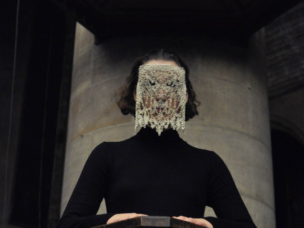
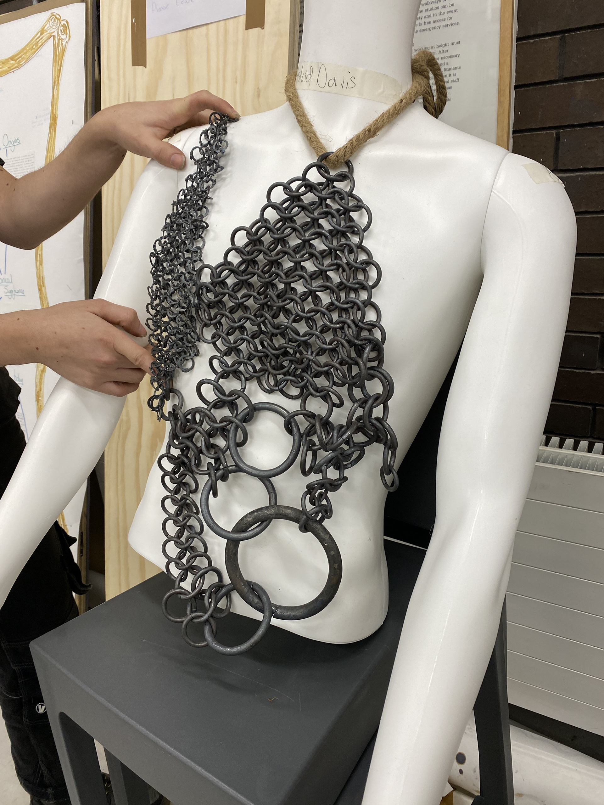
Chosen design

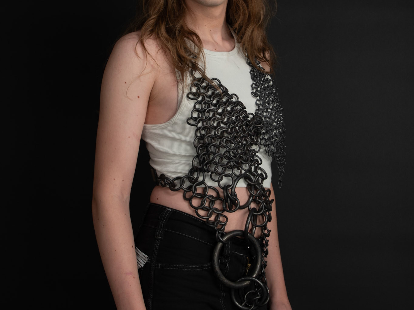
The design intentions behind this piece is to create a wearable that provides protection whilst also empowering the individual. I am working with the transfeminine body looking to transform the traditional characteristics of the male body into a more feminine presentation. The differing densities of mail seek to provide varying levels of protection and coverage, the chest being the thickest for modesty and to shroud the body underneath. Whilst the larger chain draws the eye away and exposes less sensitive areas. The raised steel plate sections provide impenetrable defence and deflect the viewers judgements. Finaly the lower plate section intends to emulate the feminine hourglass figure
The mail section will be forged from differing sized steel rods. The plate sections will be steel sheet raised and riveted together, this needs to be sampled and experimented with. The lower section will be made from both raised steel and the plate mail that I have previously tested.
Modeling the rest of the design
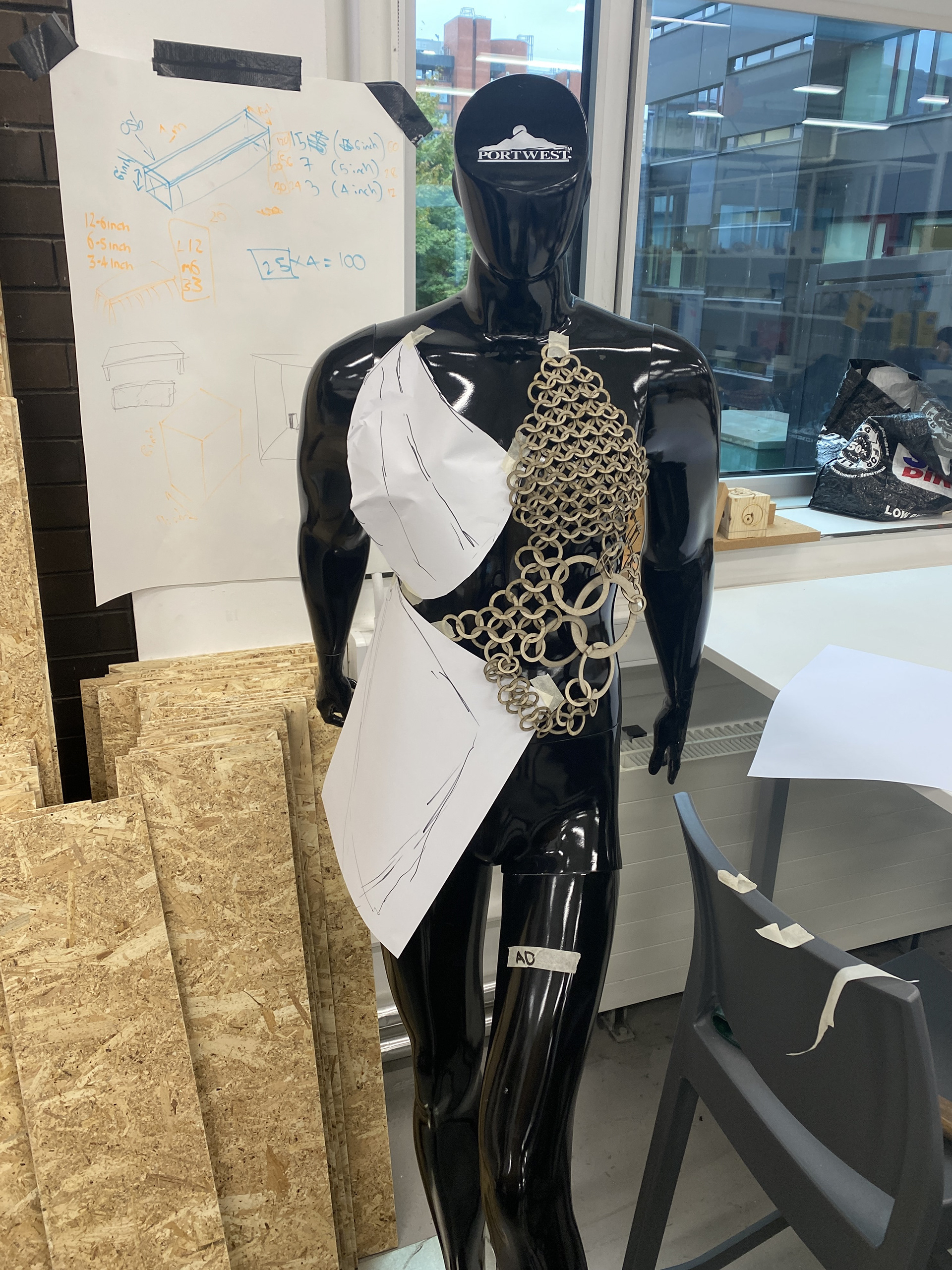
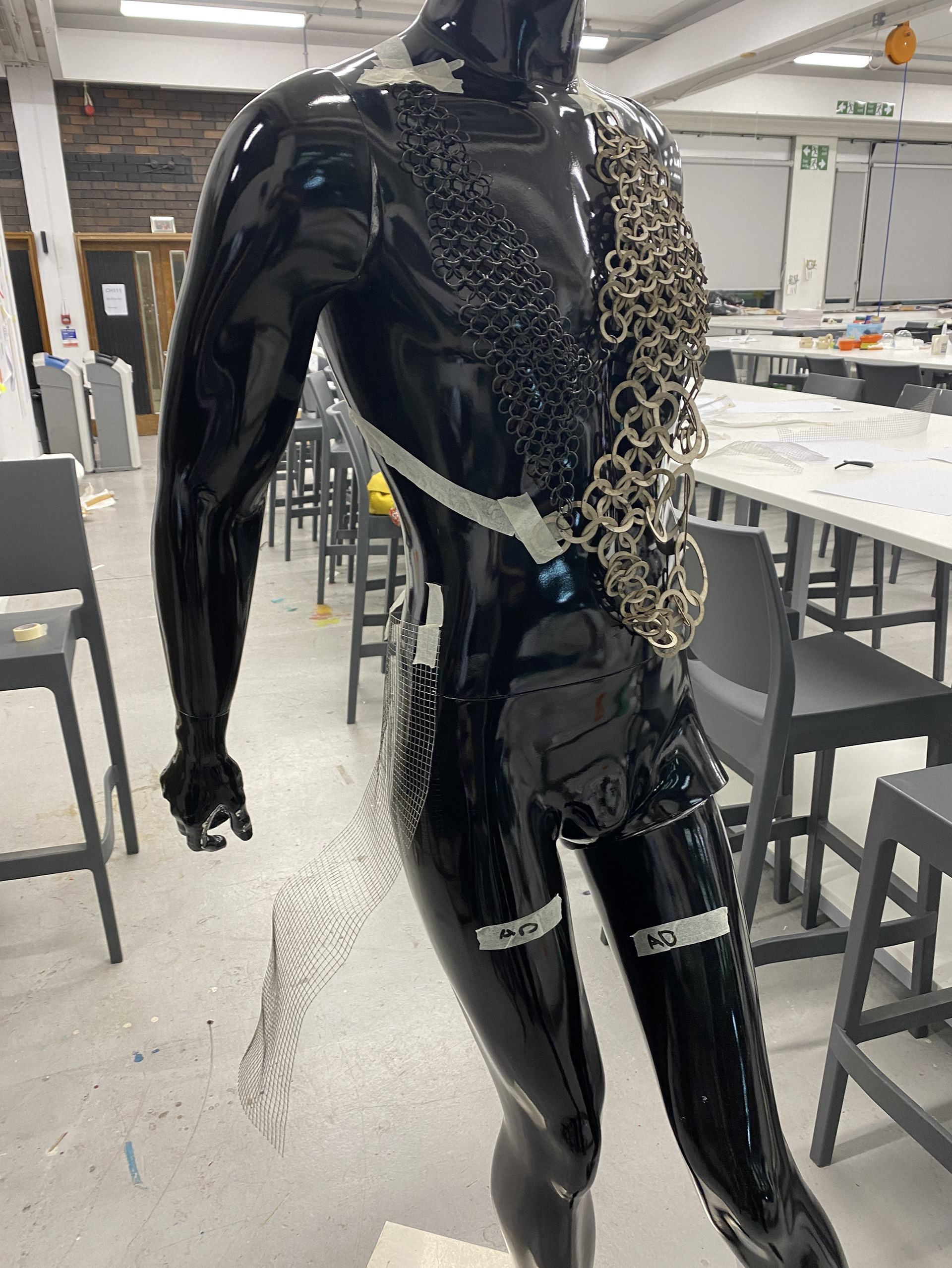
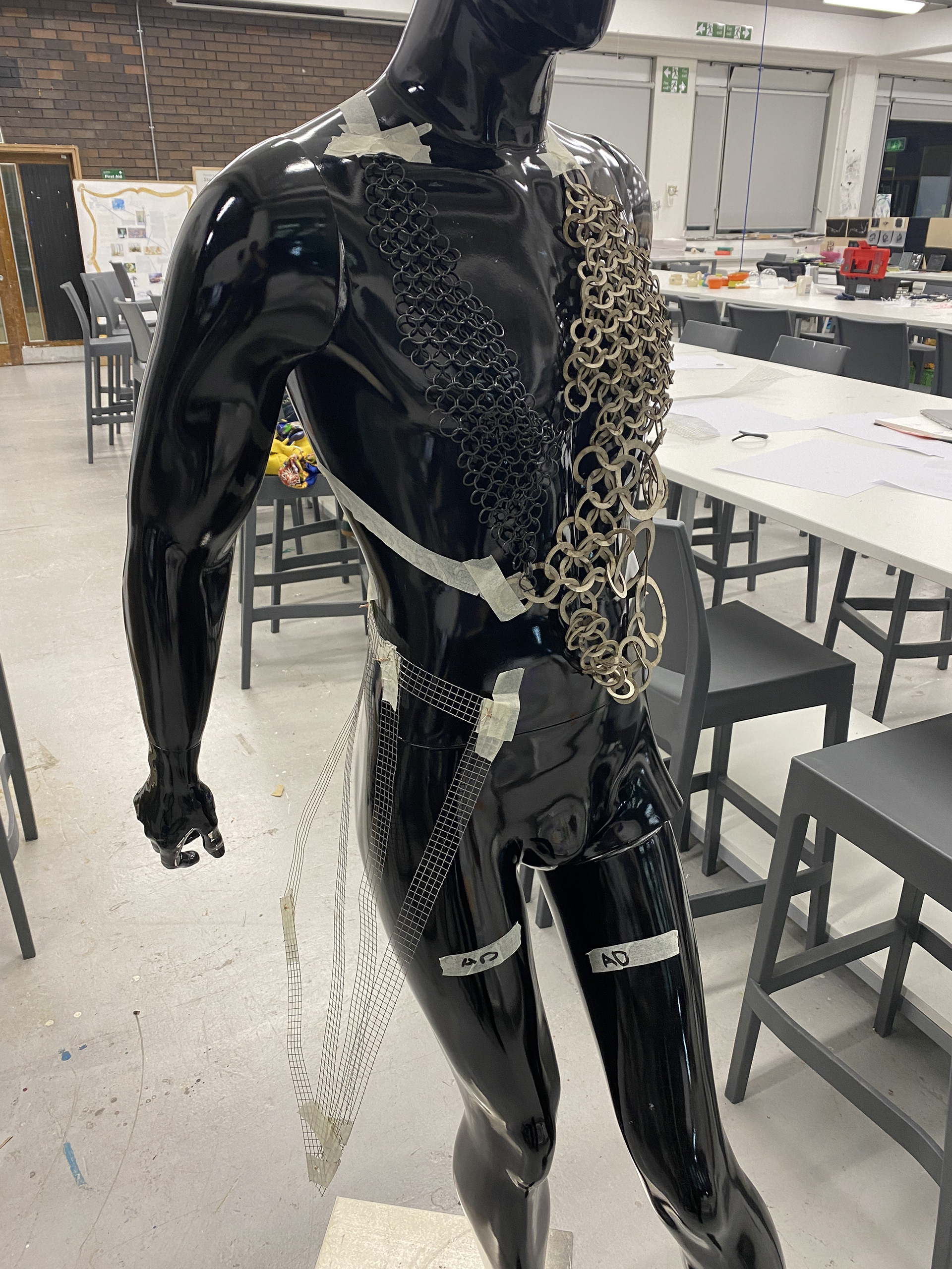
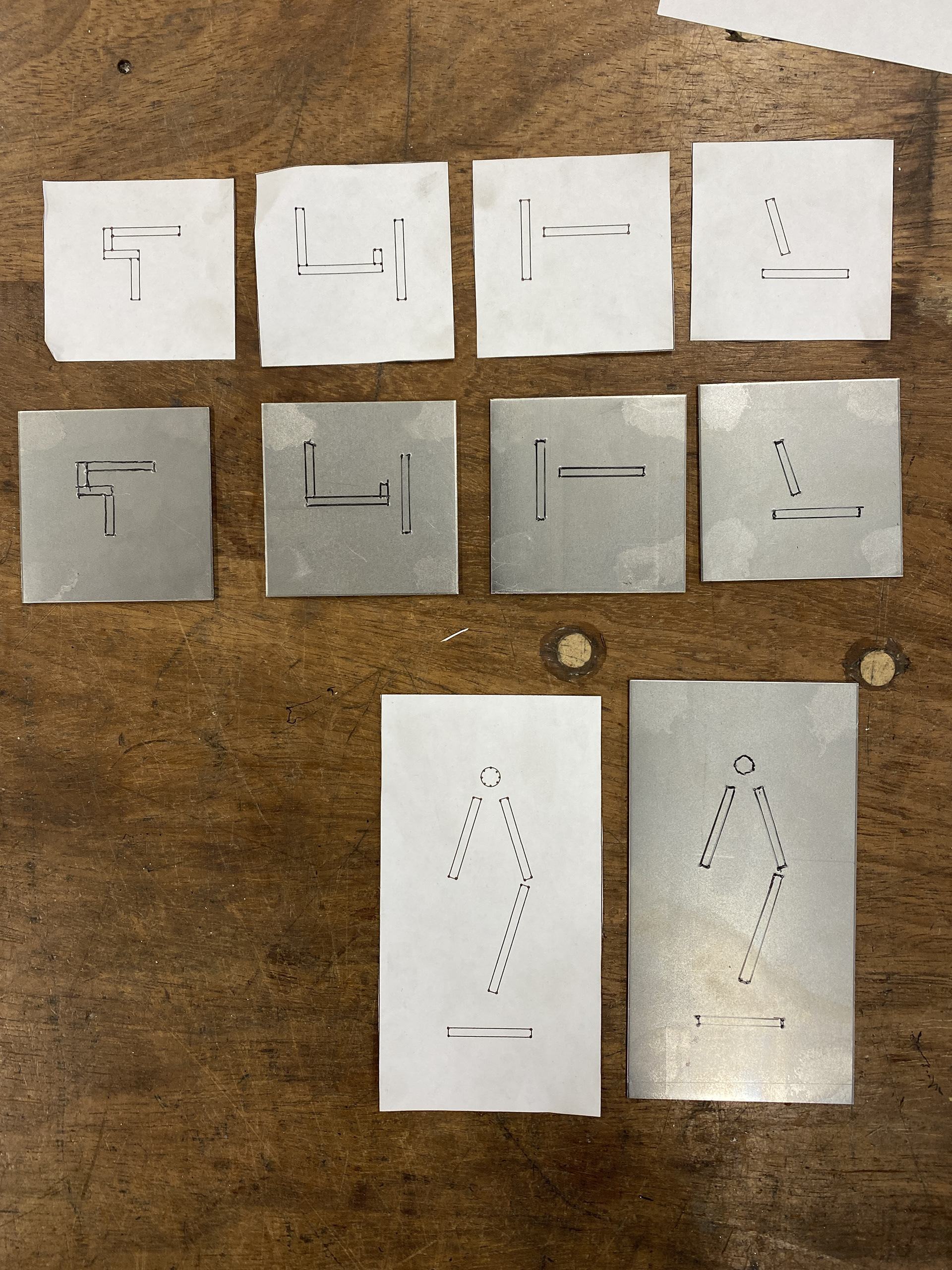
I started to mark out the different sheet metal sections using paper as a rough suggestion of form. I then used wire mesh to begin refining the different forms, beginning with the right of the chest. I used wire mesh as it was easy to cut and manipulate whilst keeping the properties of a thicker sheet metal. Initially I had designed this to be a 3 layered raised steel plate structure, which would be riveted together. When building this I discovered that the large and visually heavy piece was diverting from the original intentions of the piece. The form and sheet material suggest a deflection away from the chest and an impenetrable coverage. However, this visually draws too much attention and to the chest rather than deflecting it away. Additionally, the large bold form is more reminiscent of traditionally masculine armour, the feminine curves and flow of the body is disrupted.
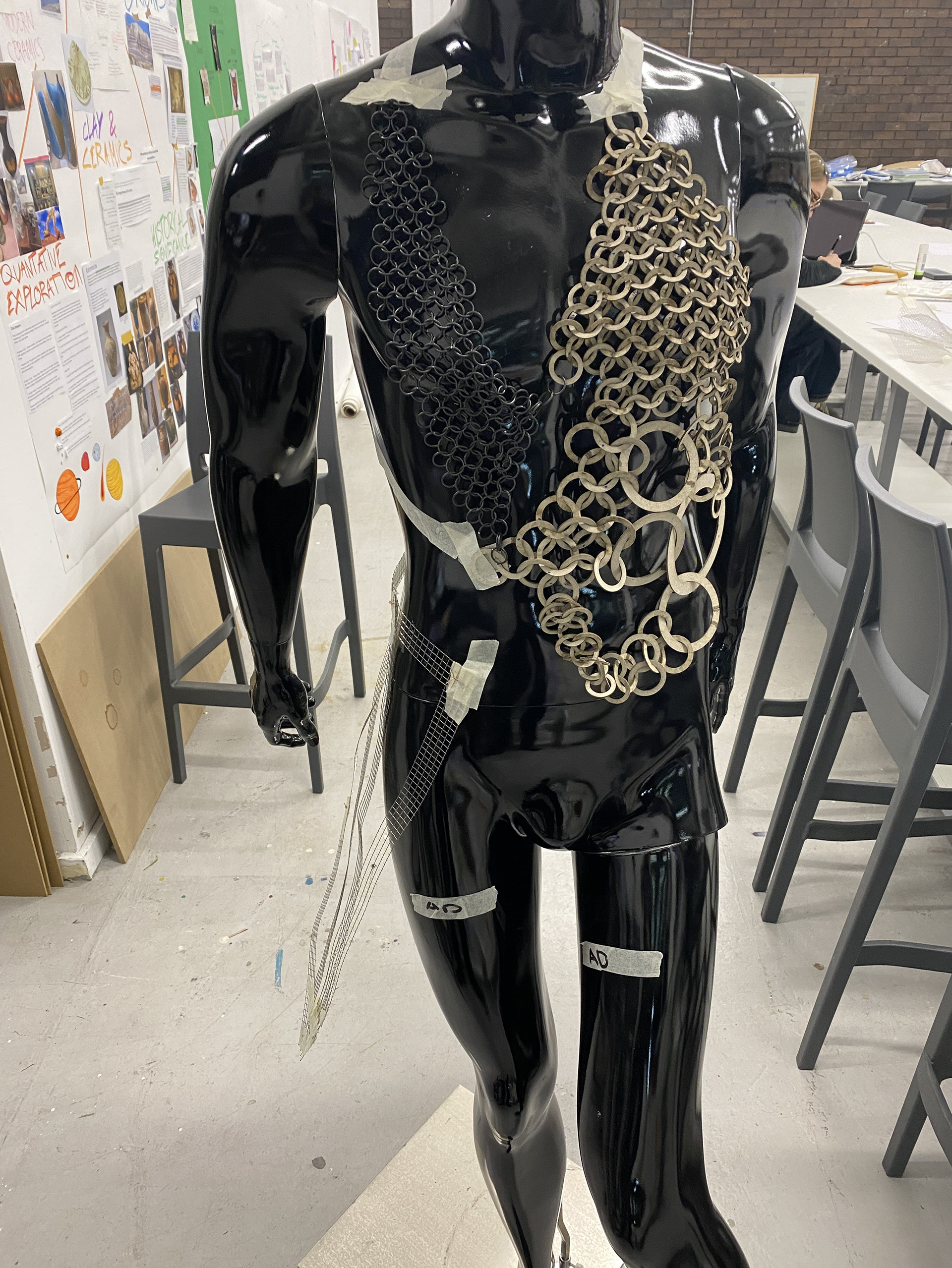
Therefore, I tested creating a smaller singular piece of plate that flows with the curvature of the chest. I investigated covering enough of the chest so that it would provide the wearer with decent coverage but also give a suggestion to the form of the body beneath. The lower v shaped neckline seeks to create a more feminine structure on the body.
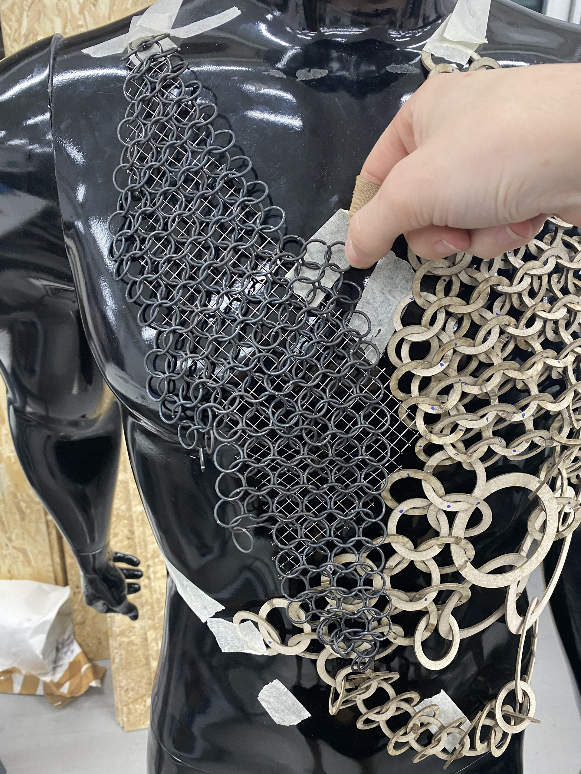
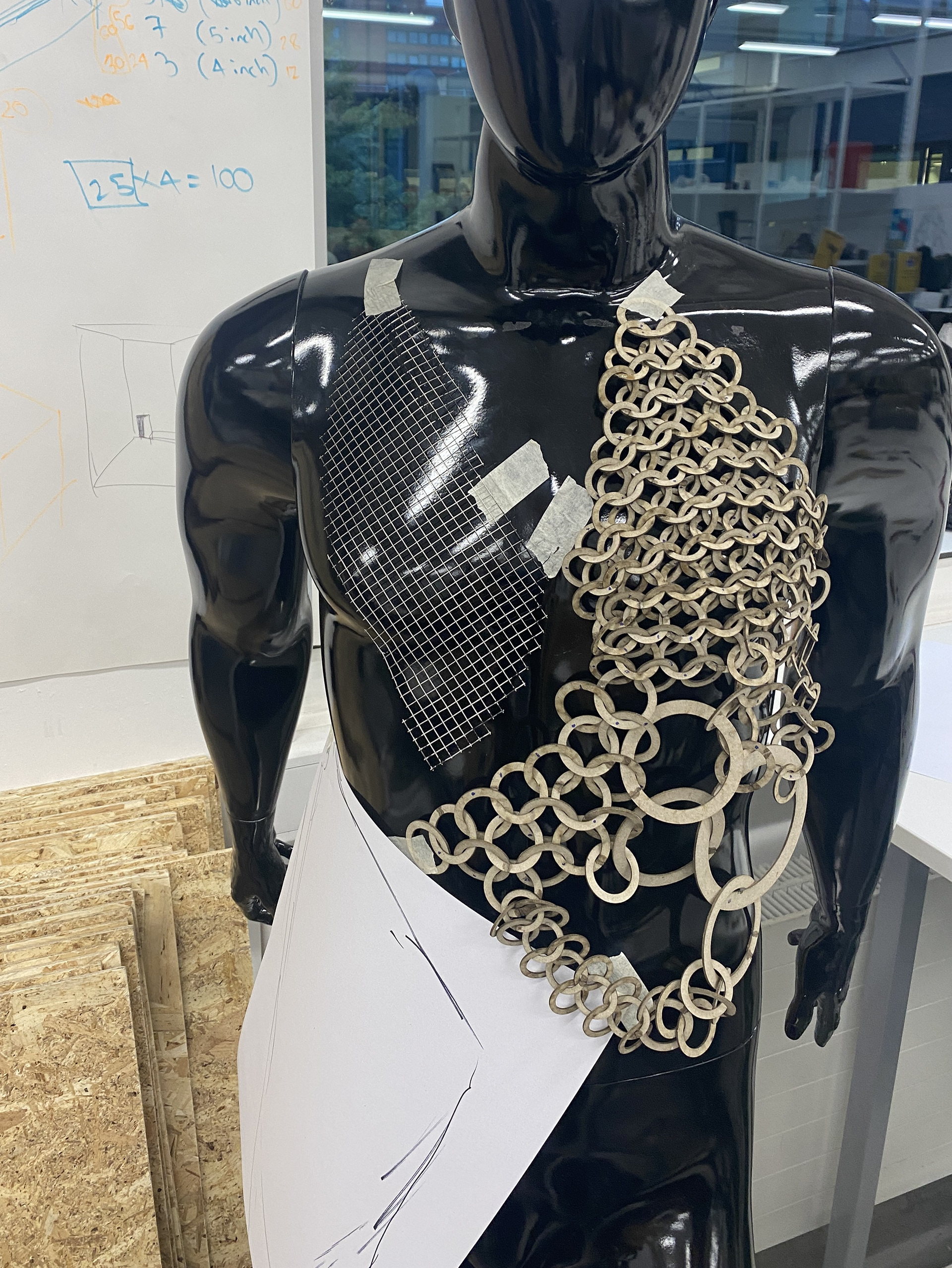
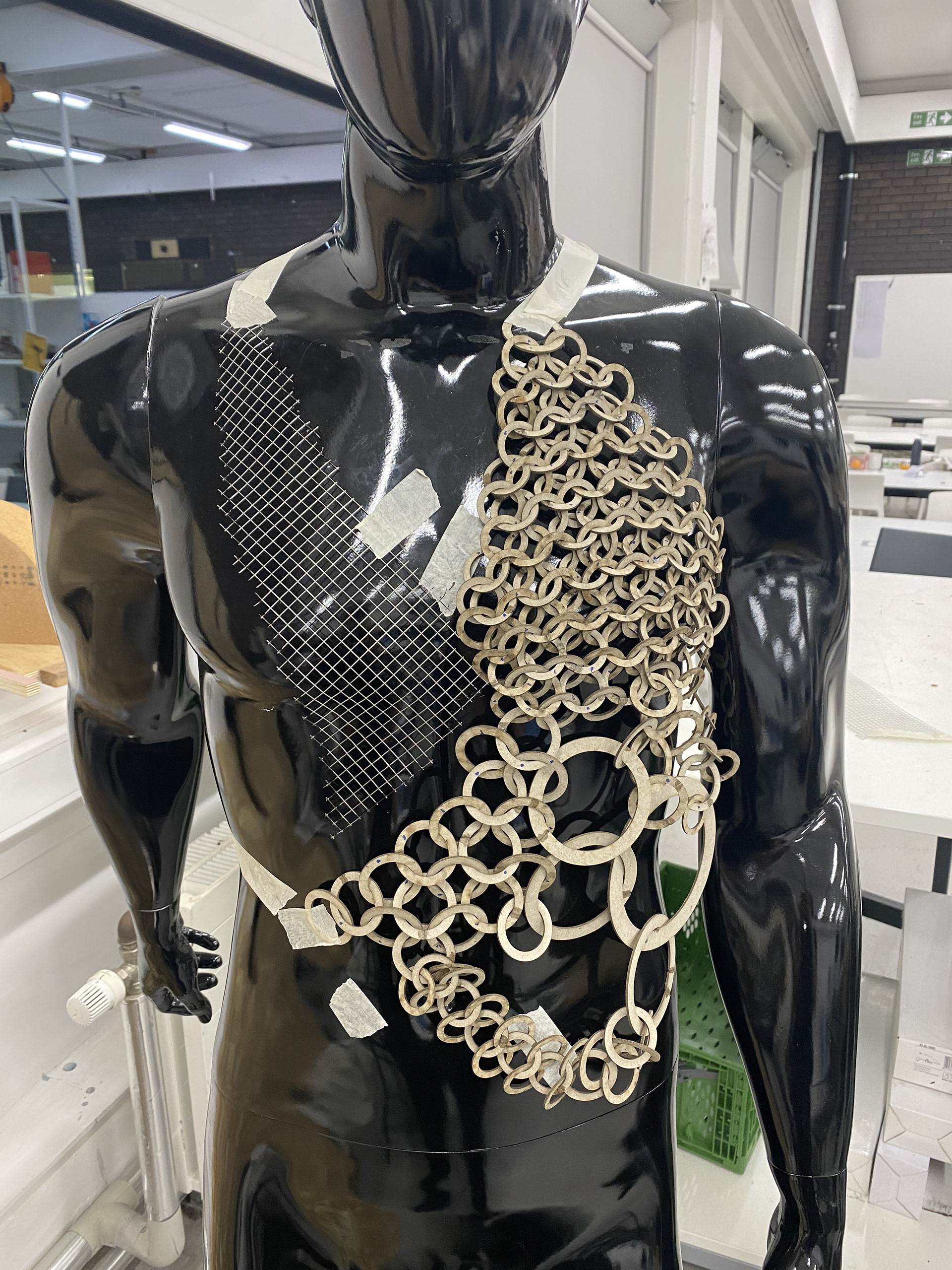
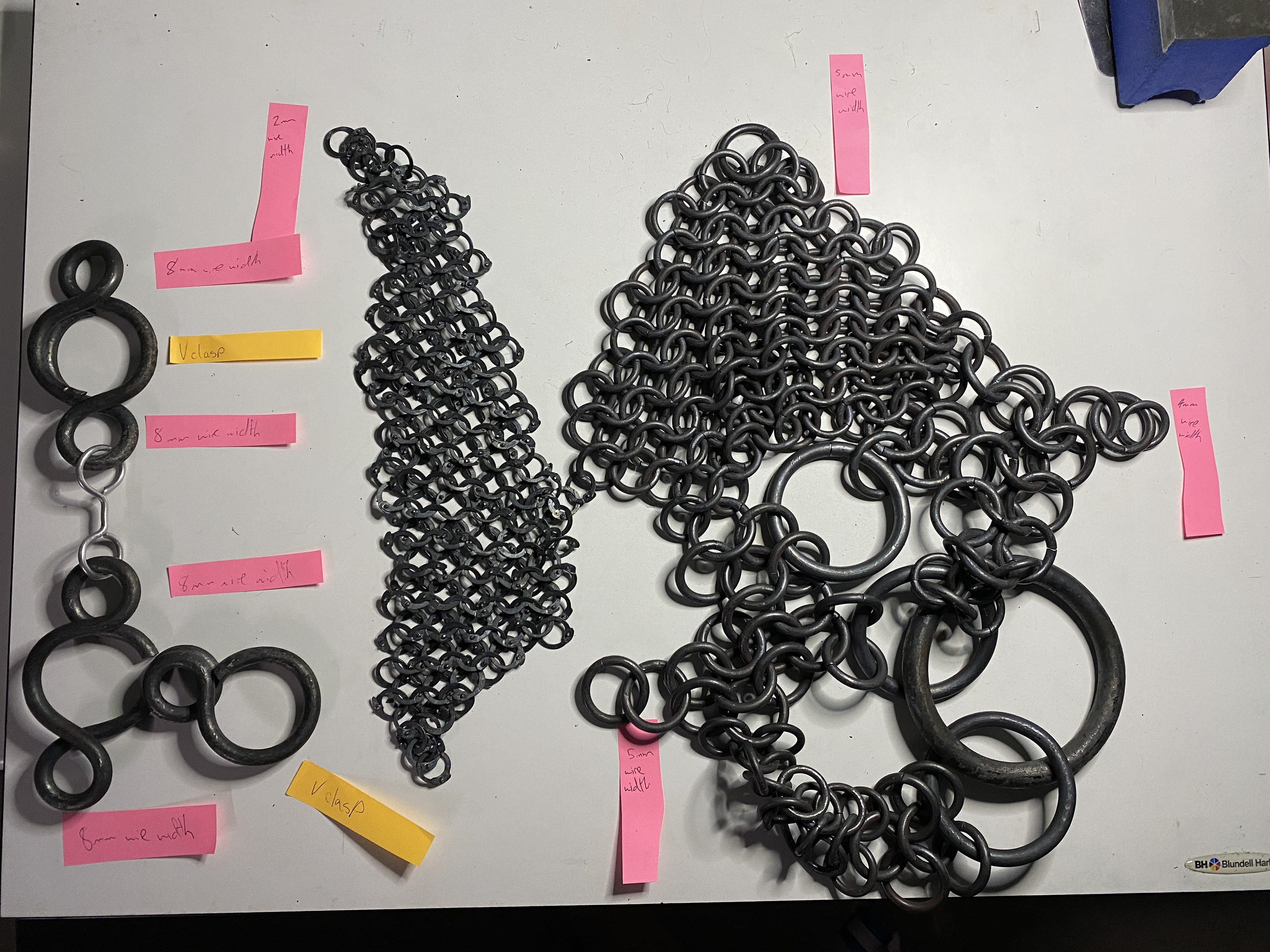
Reflecting on the chosen mesh piece I realised that the permeable nature of the material helped to reduce the visual top-heavy design. Therefore, I experimented with using the mail made from 1.6mm wire. I intend for this in the final piece to be the flattened and riveted style. This traditionally strong and secure form of protection will help to balance the exposing design.
I reworked the wire mail piece to give the structure a neater and more natural flow that contorts to the body.
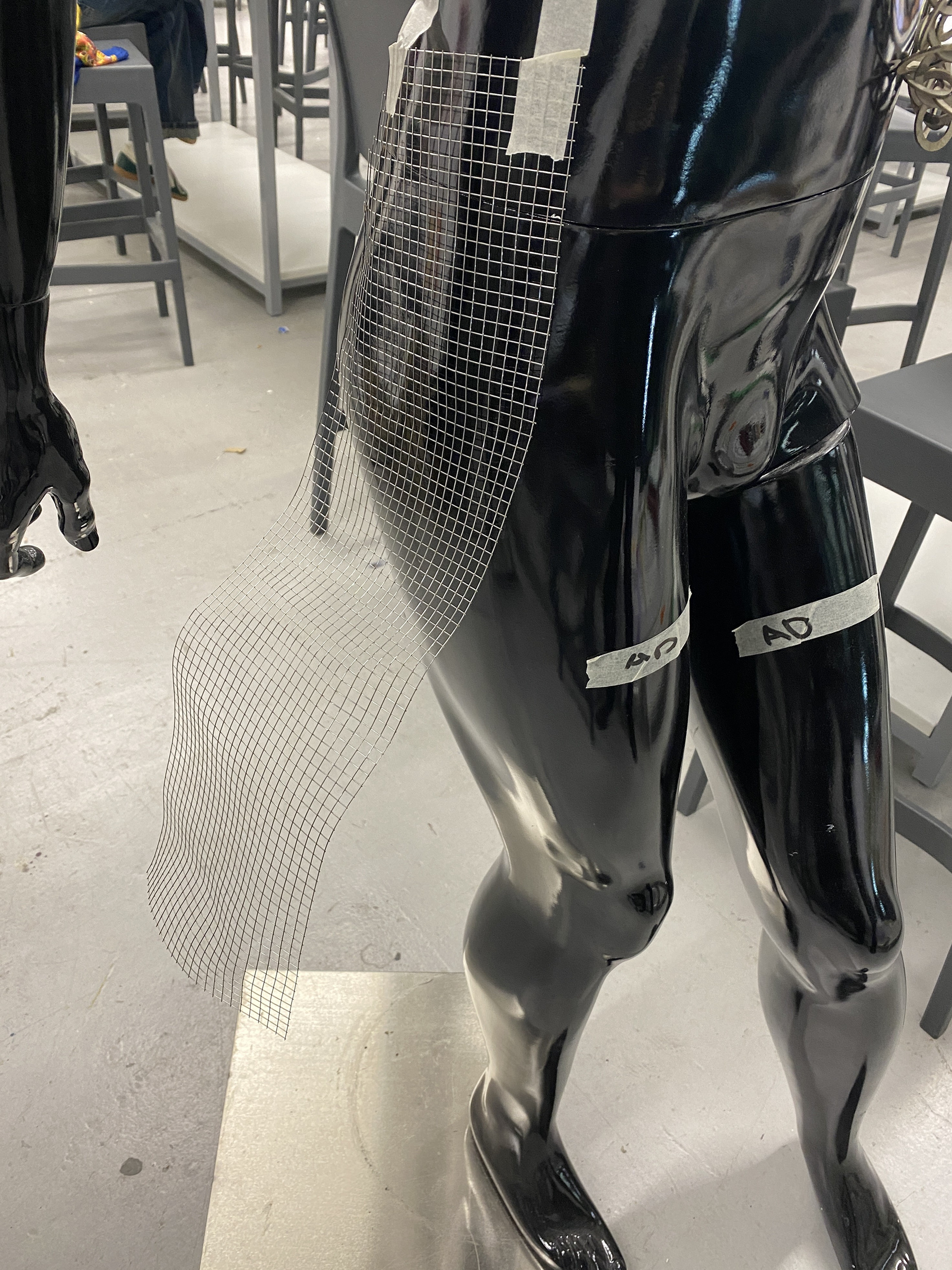
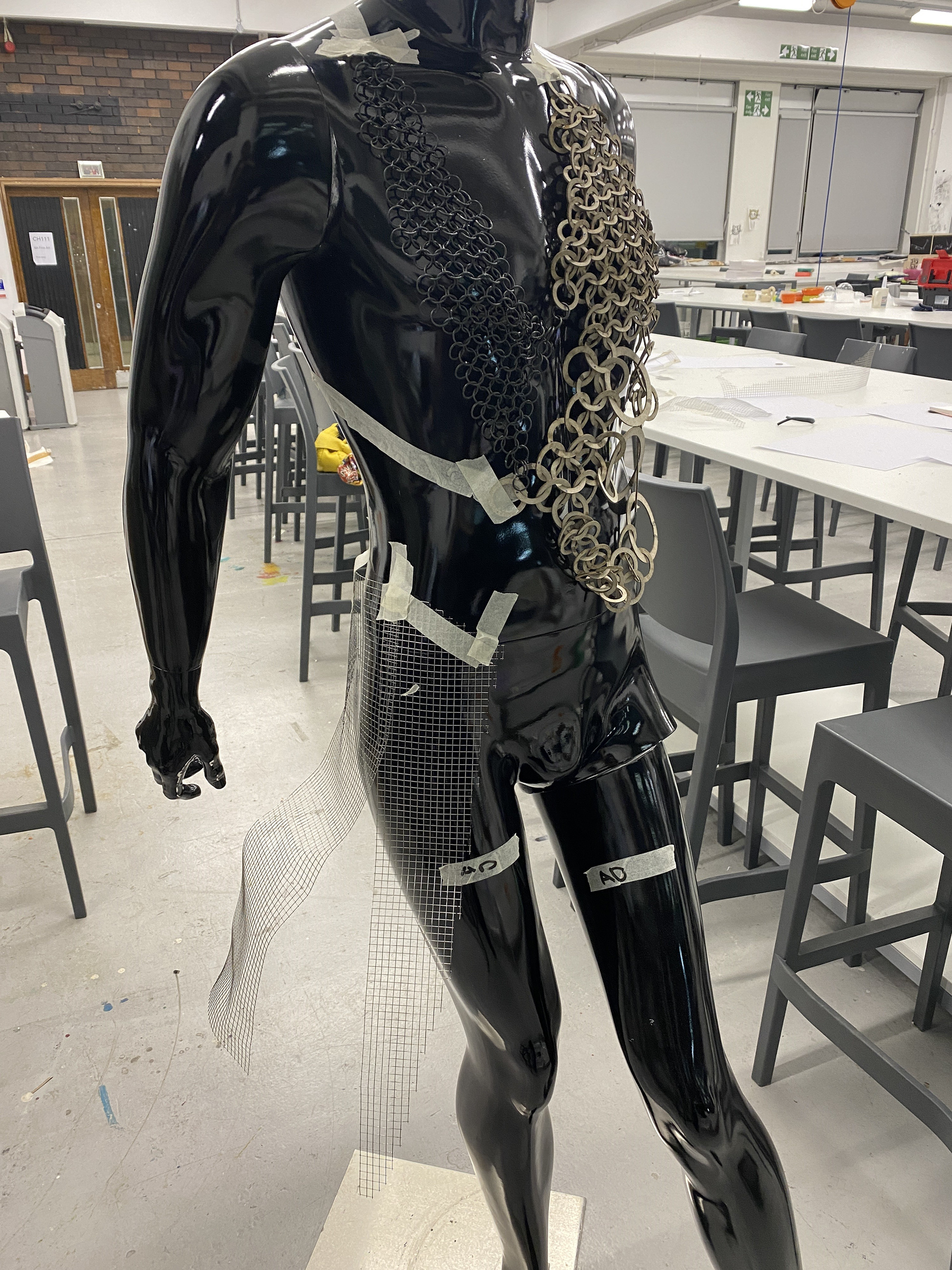
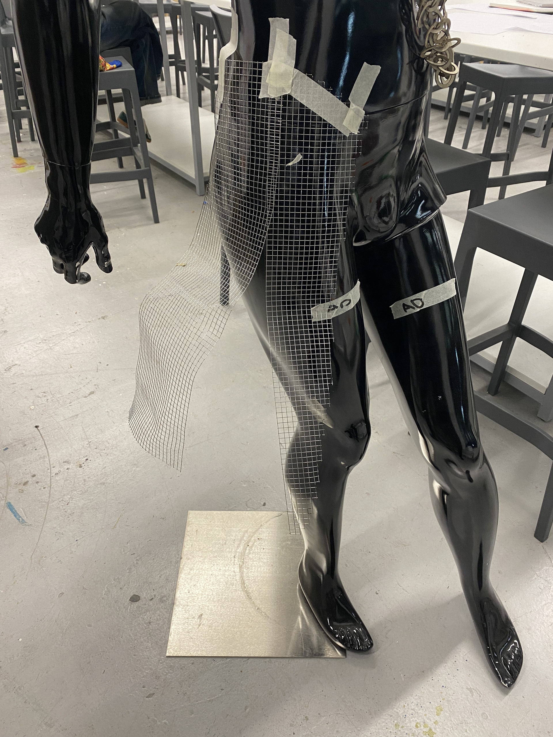
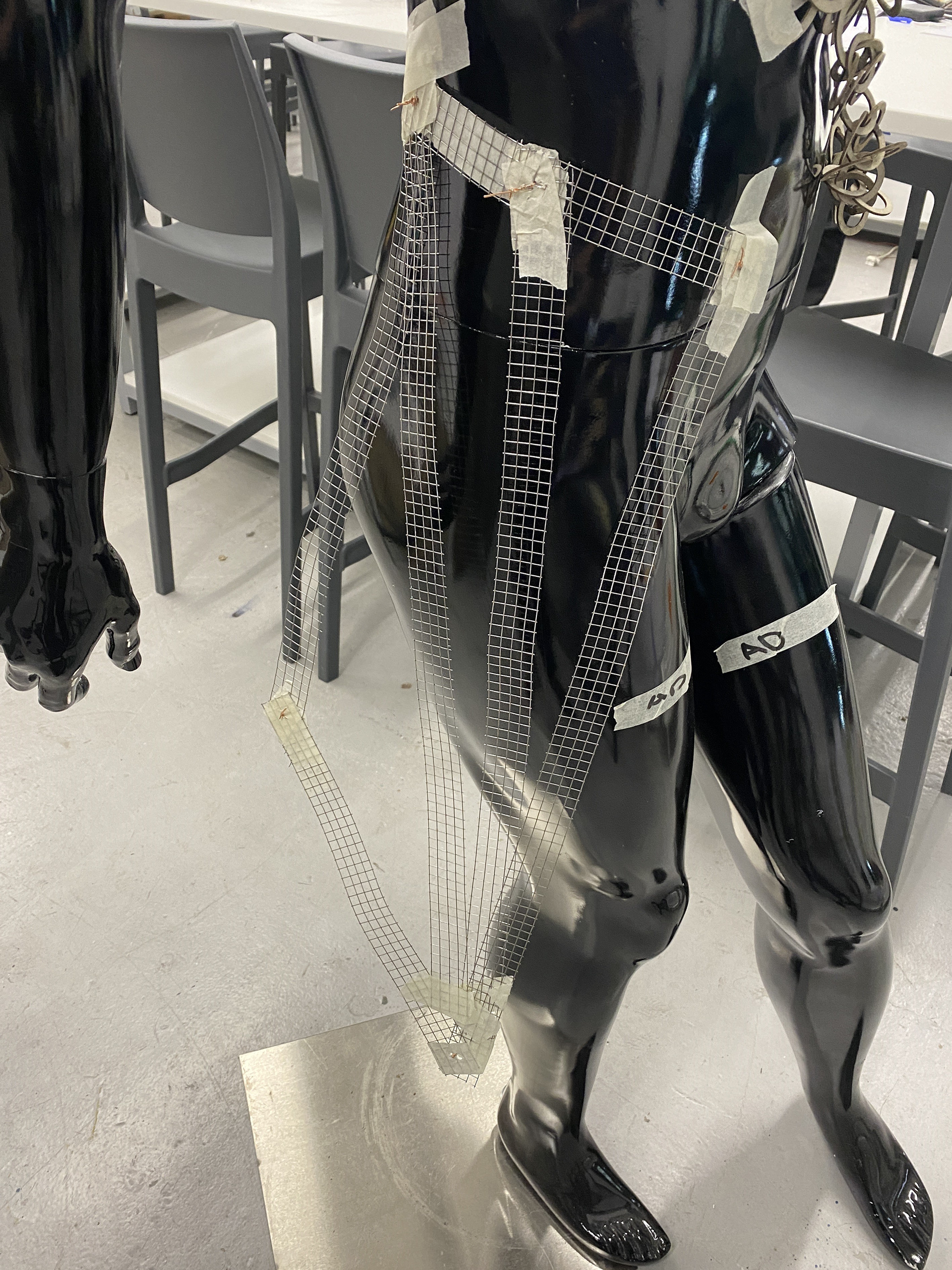
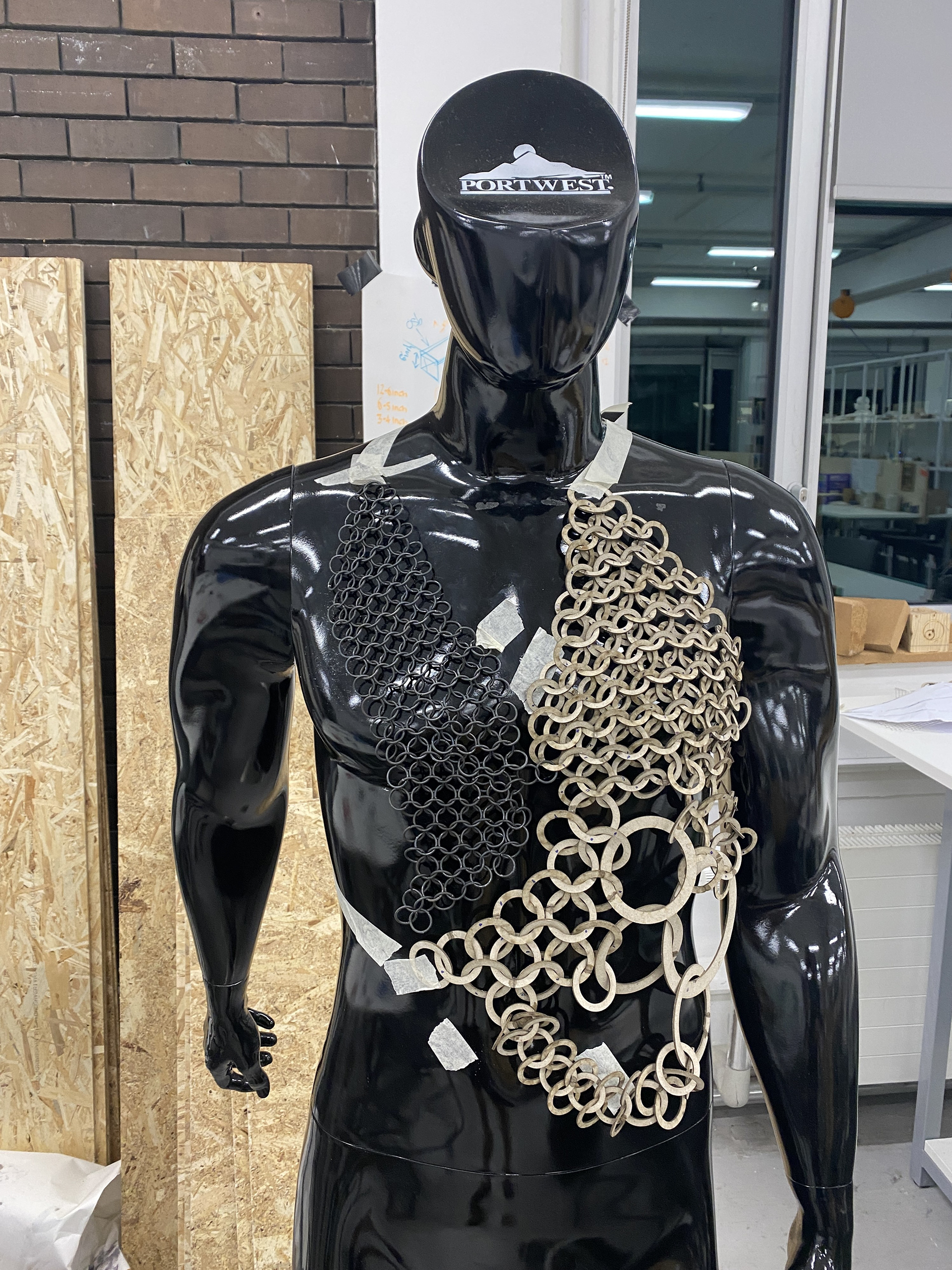
I used the mesh to test out different forms and begin to work out the require structural elements. However, every time I tried to add or alter this element it felt too much and an addition. The look was becoming too overcrowded and compositionally confused.
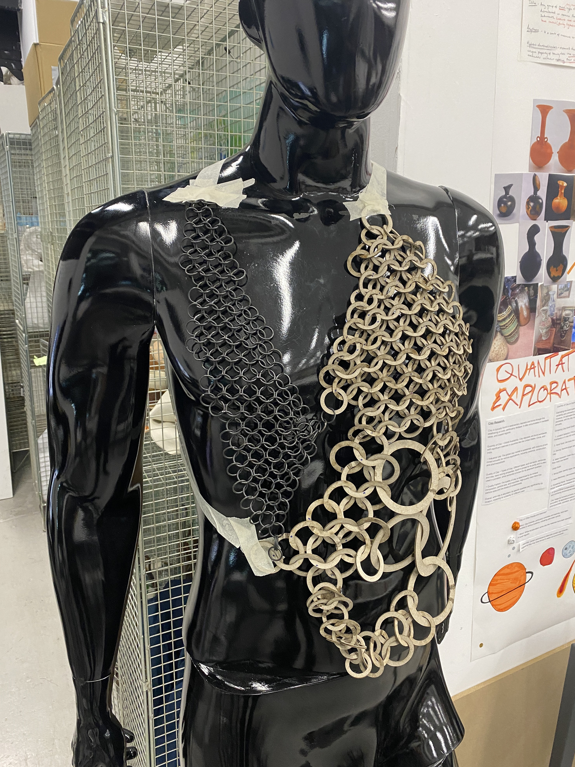
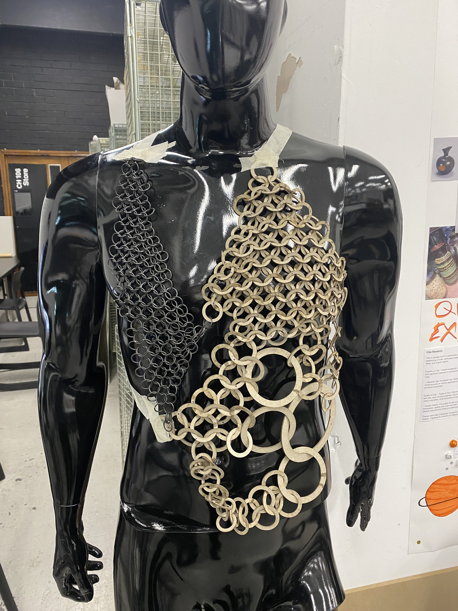
Therefore, I have chosen to drop the lower section of the design and only continue to develop the chain mail torso. I believe that there is room to explore the different elements and samples that I have developed further in S&R. I want to avoid trying to include too much into one piece, which will dilute the overall look and narrative.
Making the front mail section of the piece

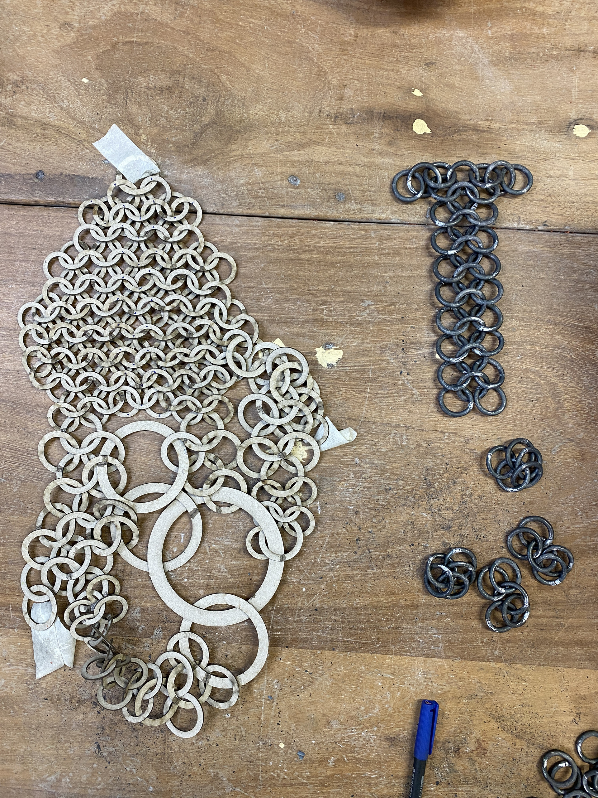
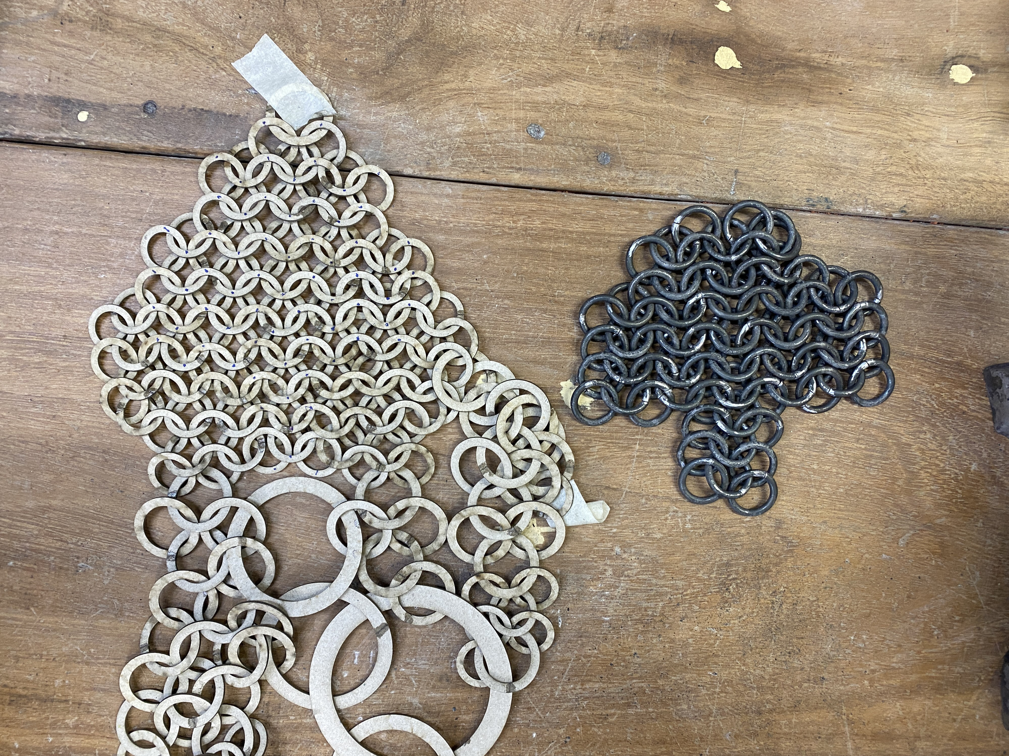
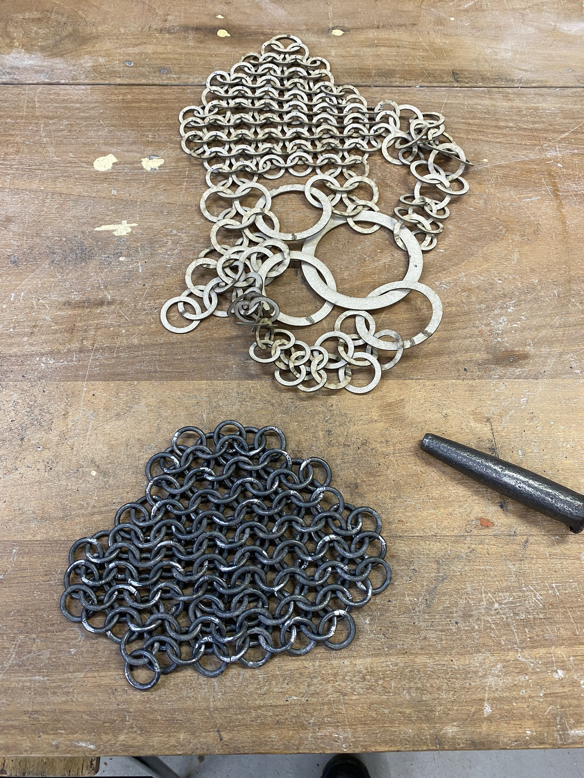

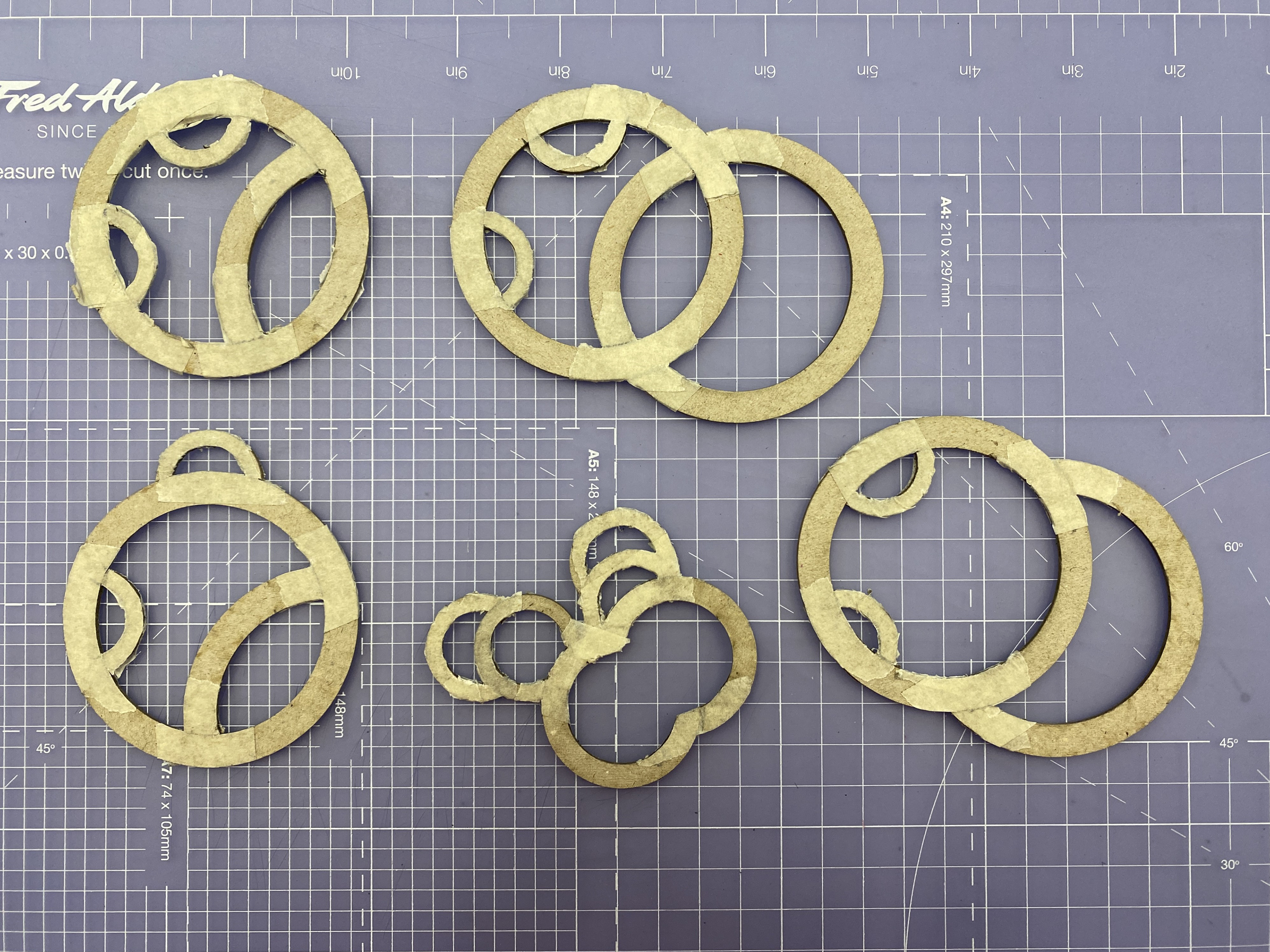
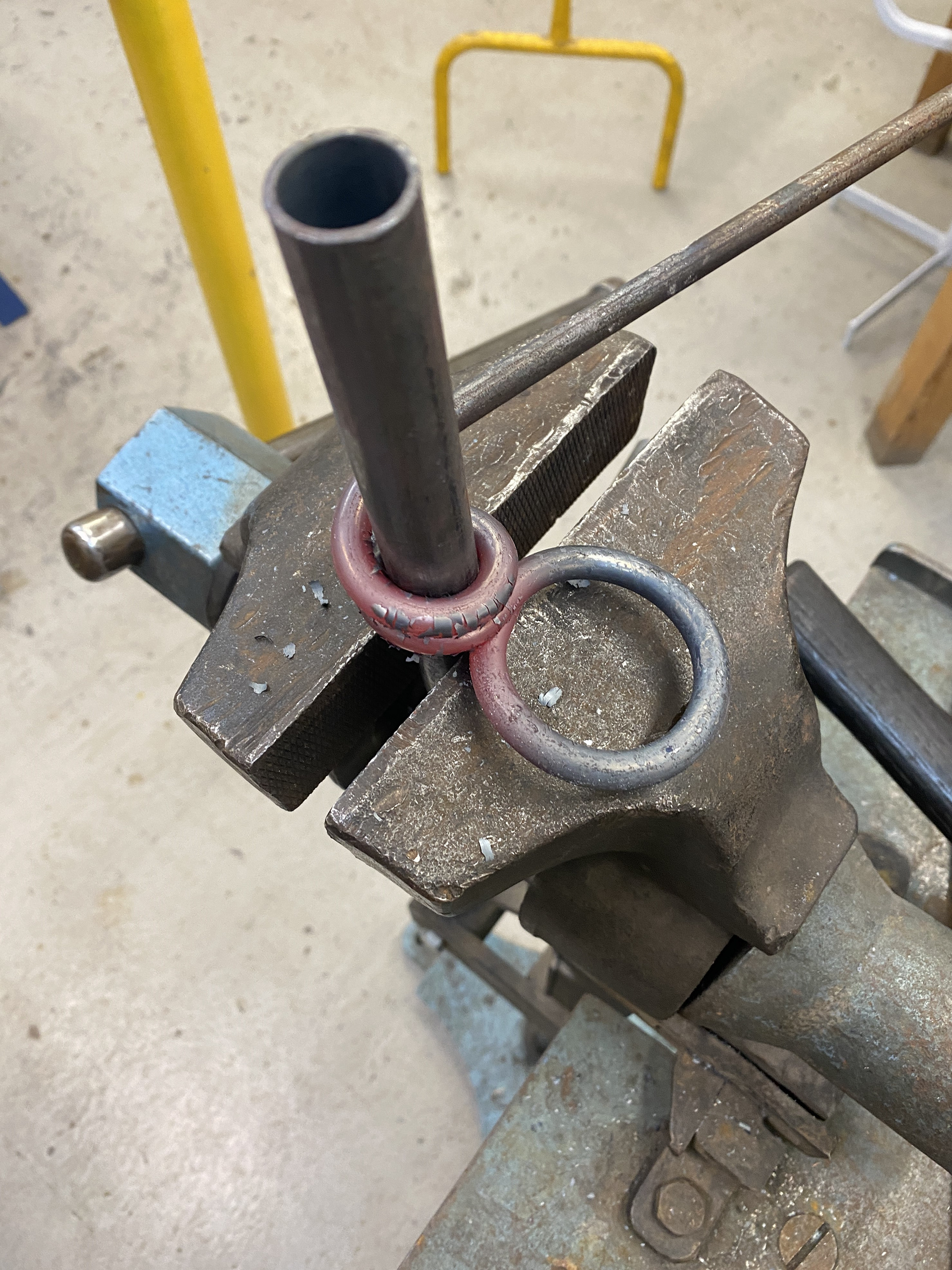
To make the larger forged chain section I repeated my previous method of hot coiling the steel rods and then cutting them into individual links using an angle grinder. I found that with such a large quantity cleaning up the burs was more consistent and faster using a diamond grinding bit in a small rotary tool than a file. Once the links were uniform, I begun weaving them together using the laser cut cardboard model as a guid and marked off the links as I went using a pen.
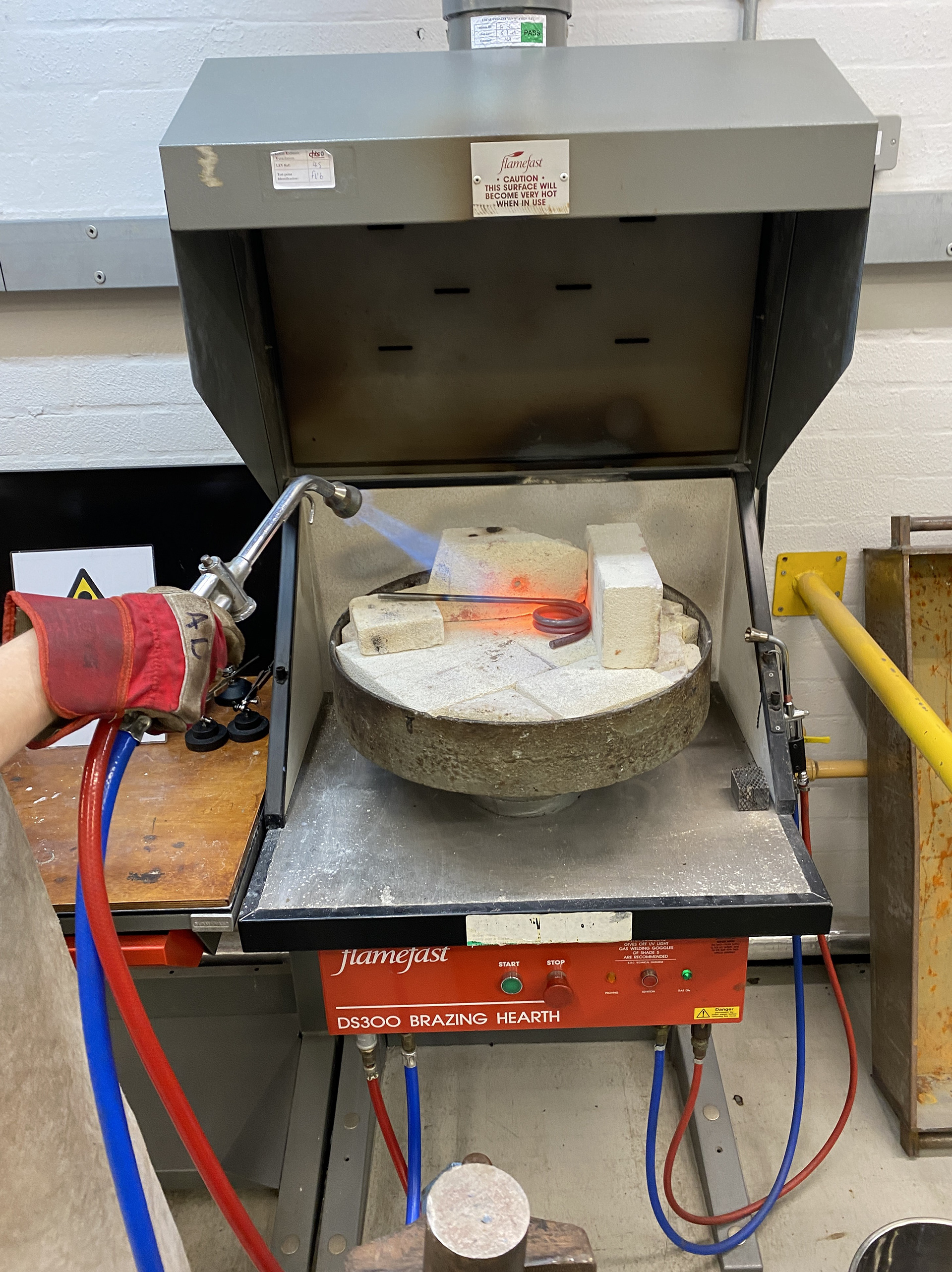
One problem area was the forge went out of action before I could form the 4 larger links. However, I managed to overcome this by heating the steel on the hearth using the gas torch and building up a semi enclosed brick wall to trap the heat.
To produce the riveted chain section, I undertook the same process as before, as shown in the video above. Once again, I used the model as my guid to weave the piece and worked downwards in rows.
The result was a consistent and strong structure. However, there has a very high failure rate between cut link and final riveted link. In total I used roughly 180 links to make the final piece, I cut 800. The failure rate was due to numerous stages throughout the process lacking consistency. The first was when I hammered the links flat, the overlap would often slip or distort, resulting in a lack of material for the rivet hole to be punched. Additionally, during the punching process a slight off-centre movement would result in a too thin wall opening up one side.
Despite extensive testing I couldn't figure out a consistent way to produce successful links. Therefore, I simply had to make enough to allow for such a low success rate. I believe one of the main struggles was my lack of experience which over time may result in a more consistent workflow. Additionally, contacting and consulting with an expert maybe my next step to improving this element of my practice.
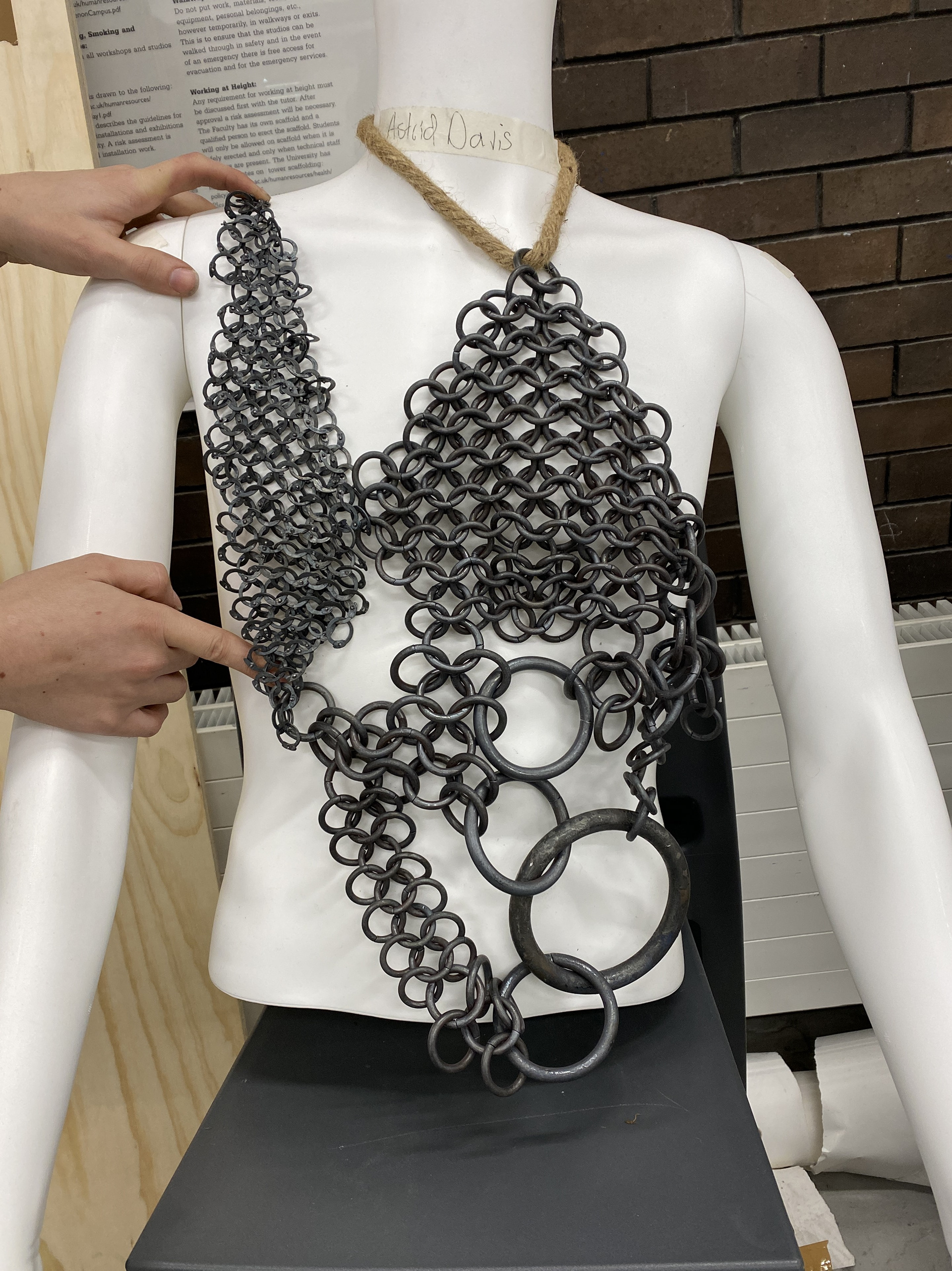
I am happy with the result of the chain; the next step is developing the straps and clasps to ensure the piece sits correctly onto the body.
Designing the straps and hardwear
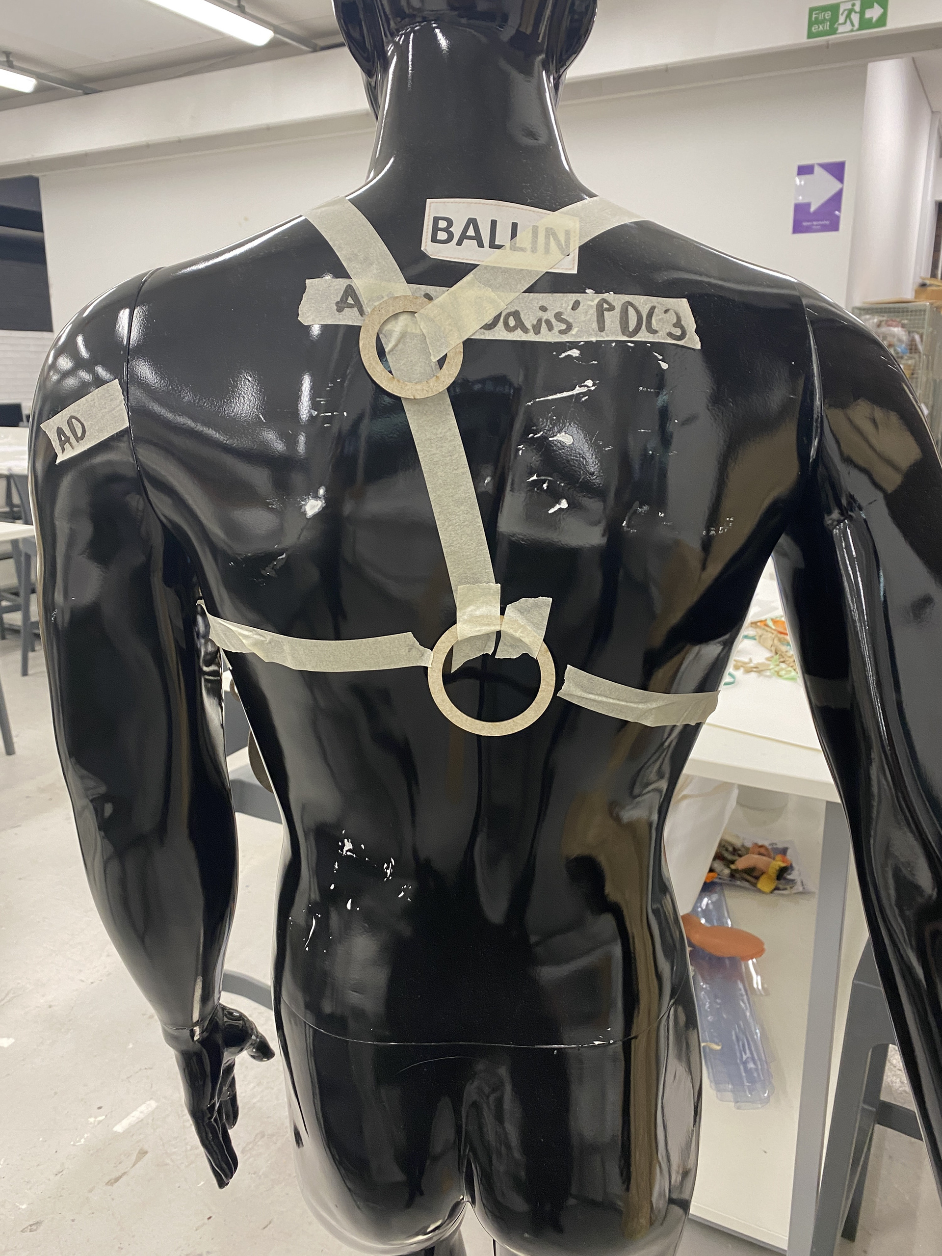
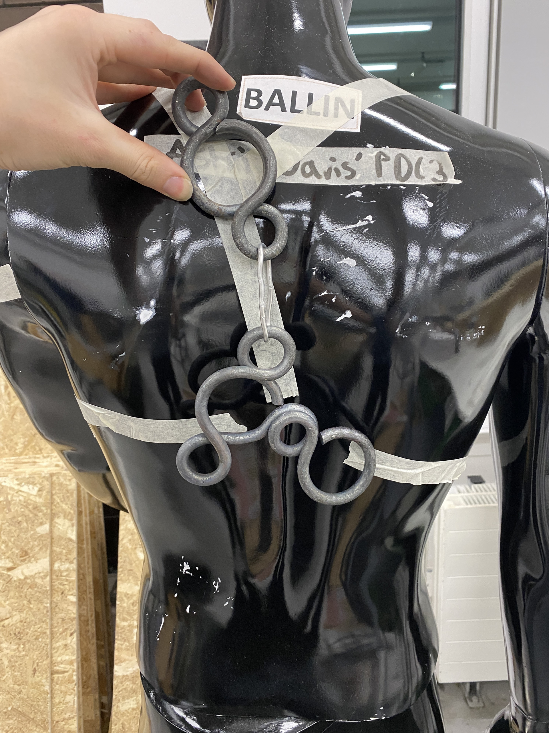
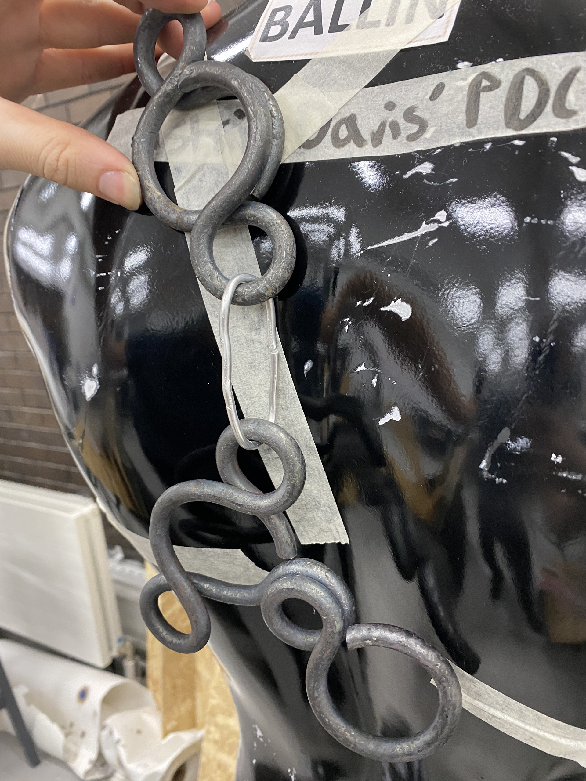
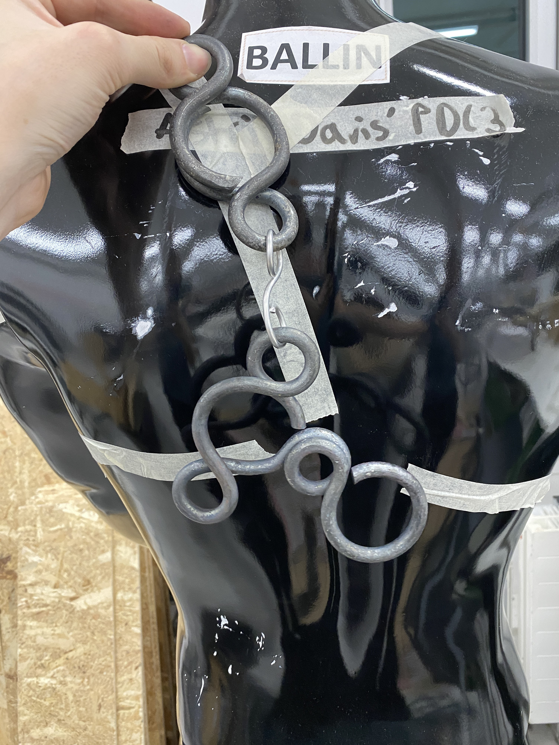
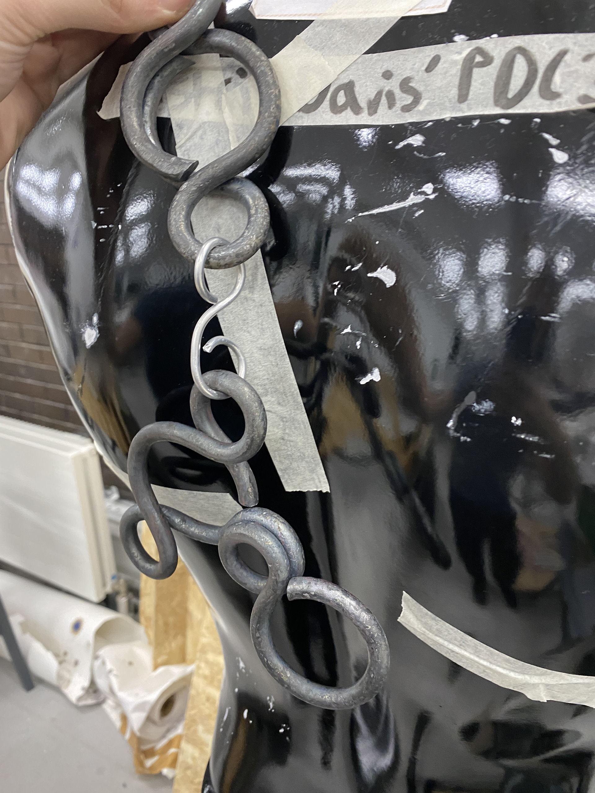
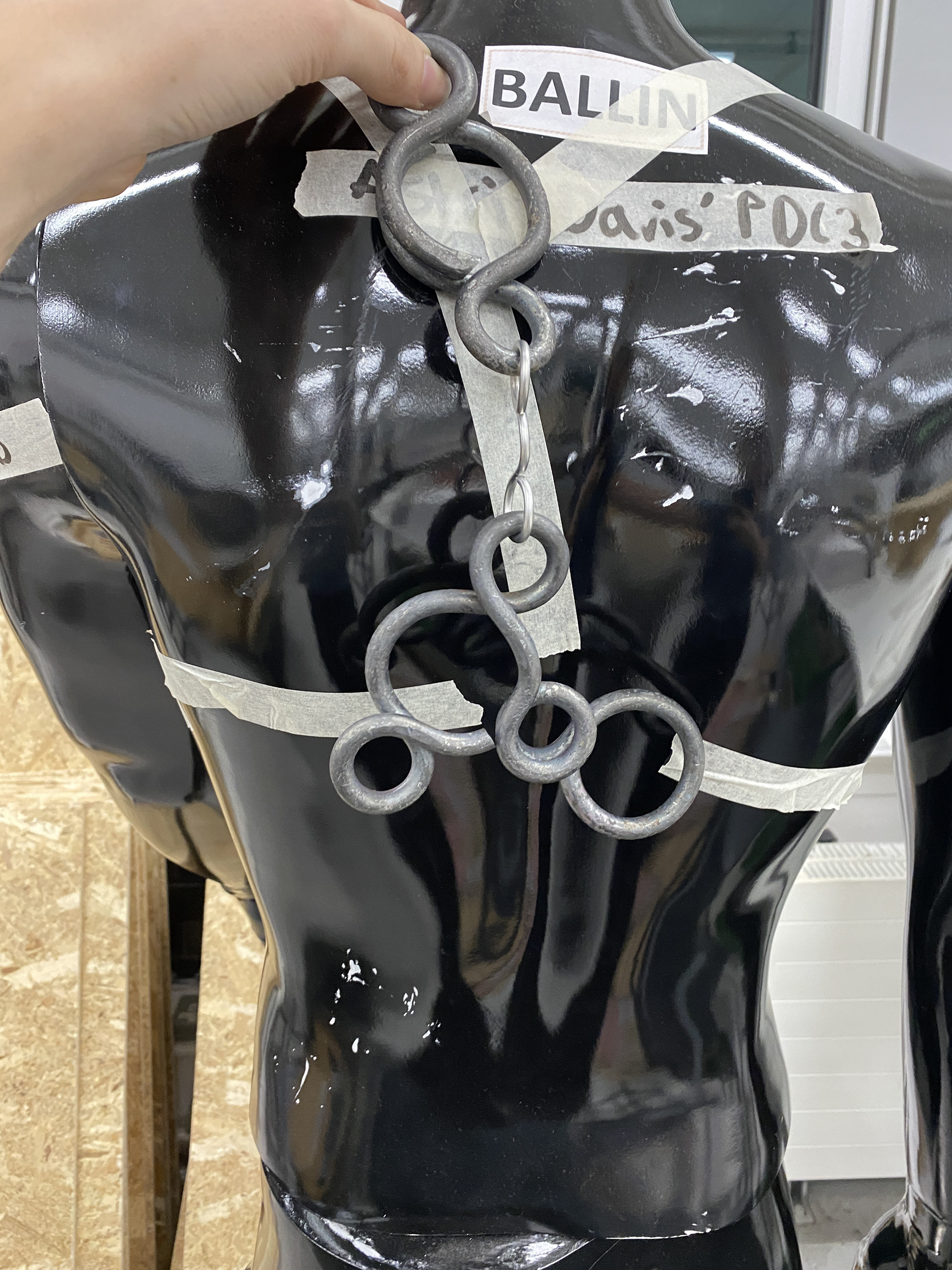
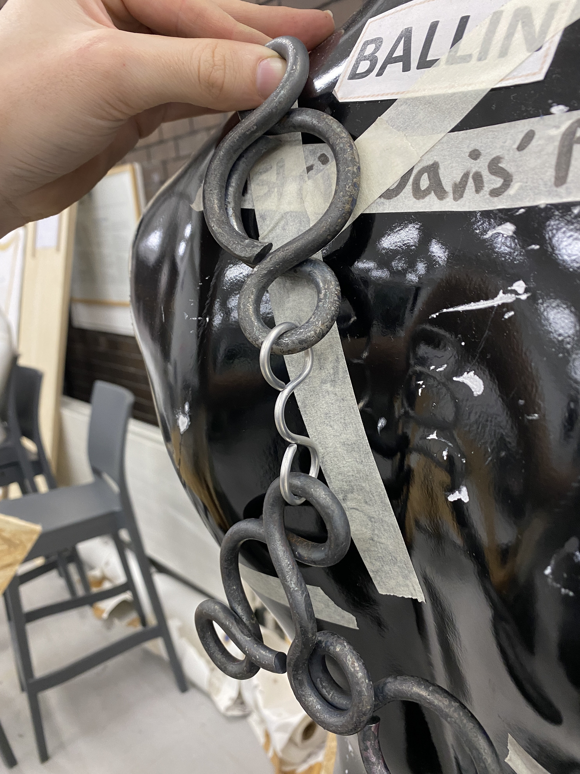
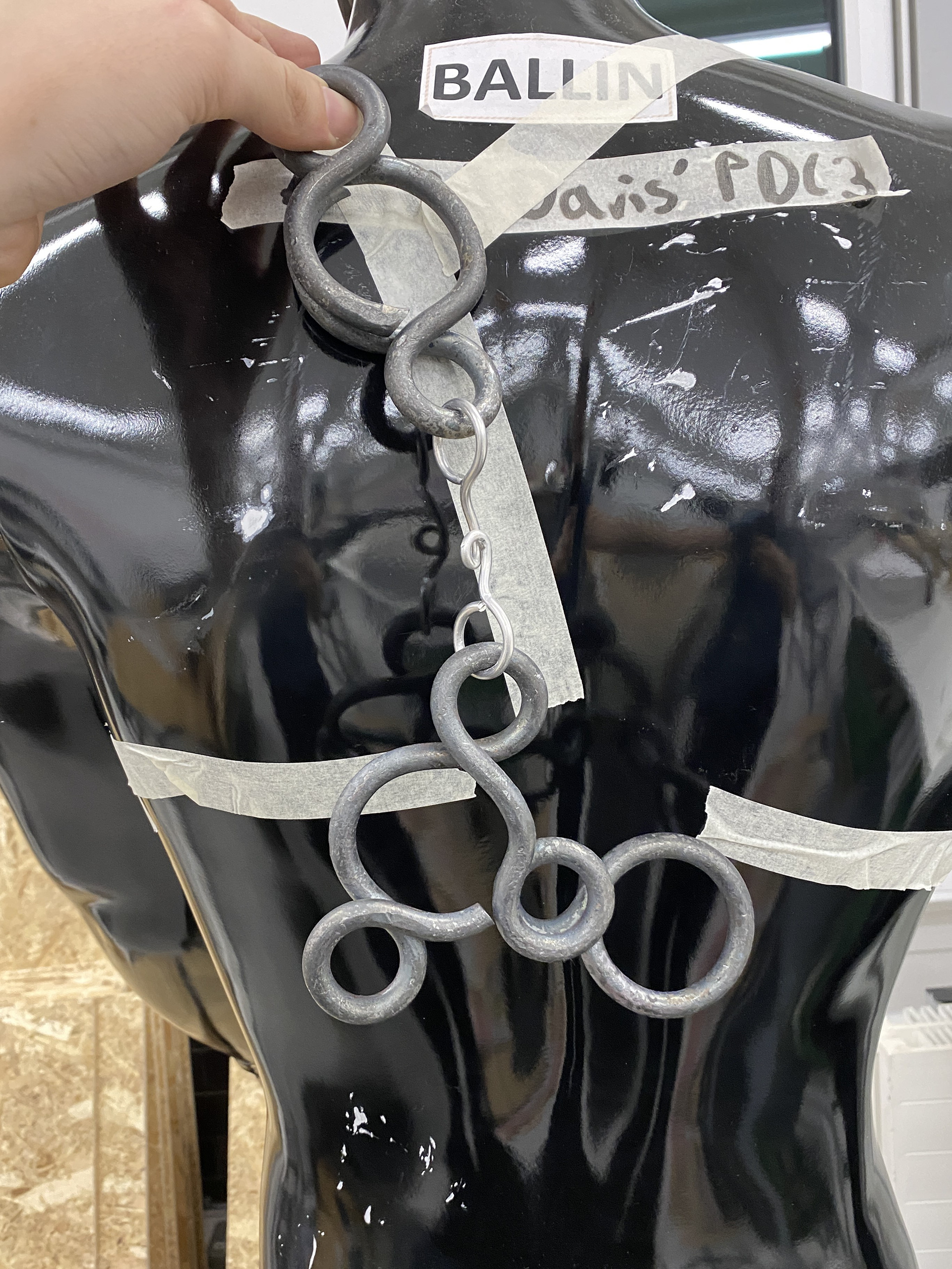
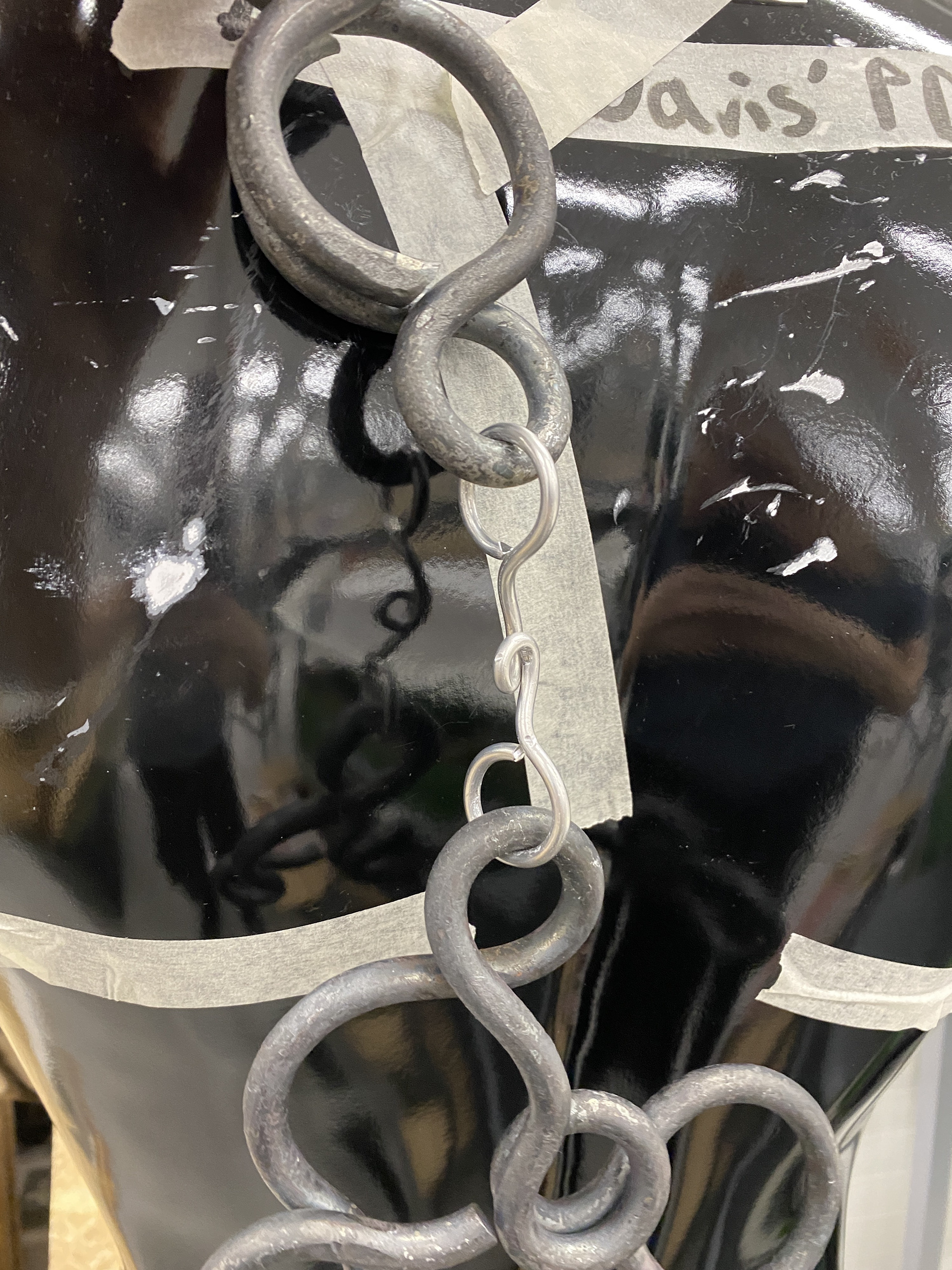
To figure out how the piece would sit on the body I taped it to the mannequin and used masking tape to lay guidelines down as to where the straps would stretch over and around the body, connecting at the back. I worked out that these would need to meet in two different places, over the shoulders meeting in between the shoulder blades and under the arms in the centre of the back.
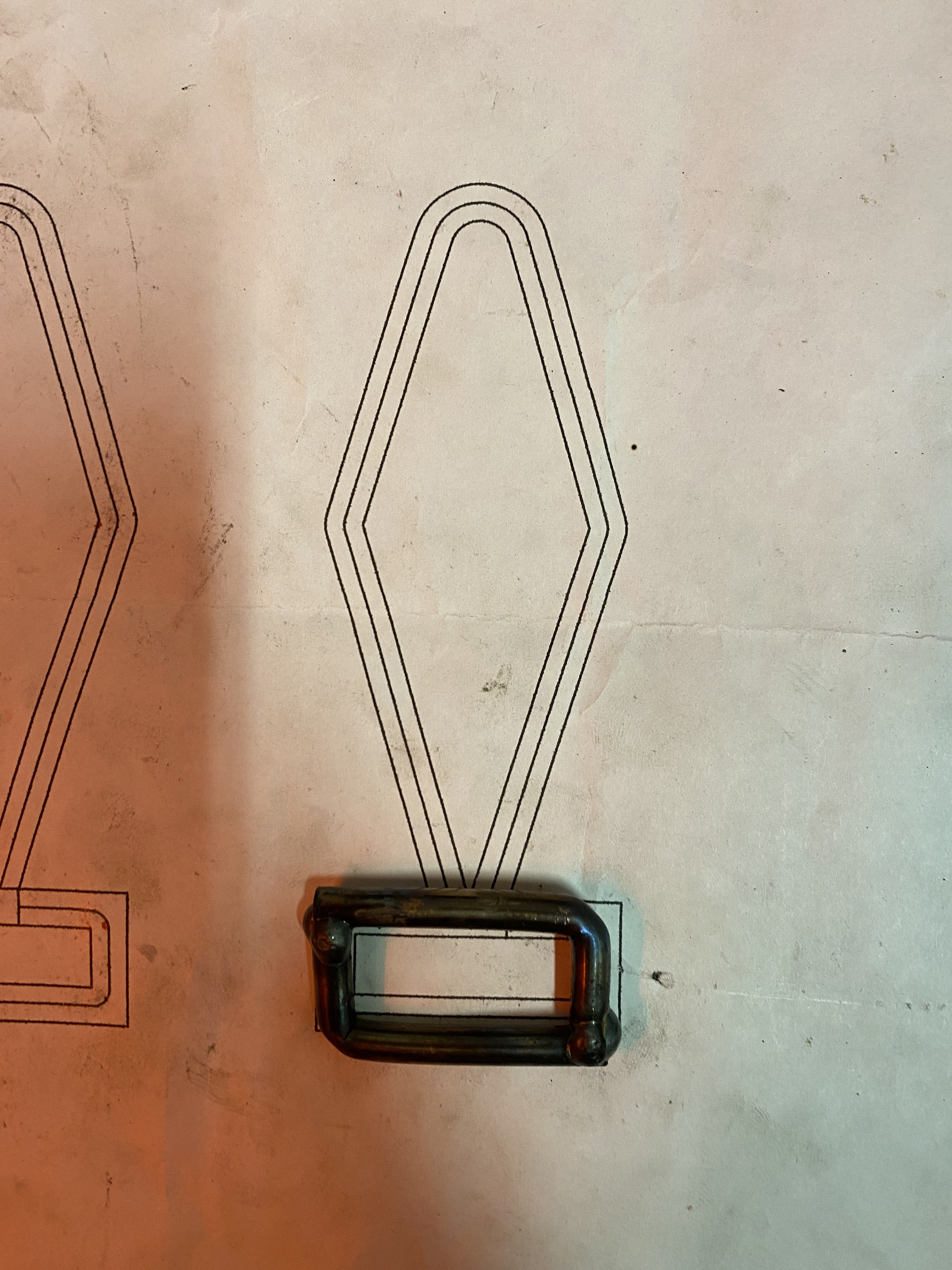
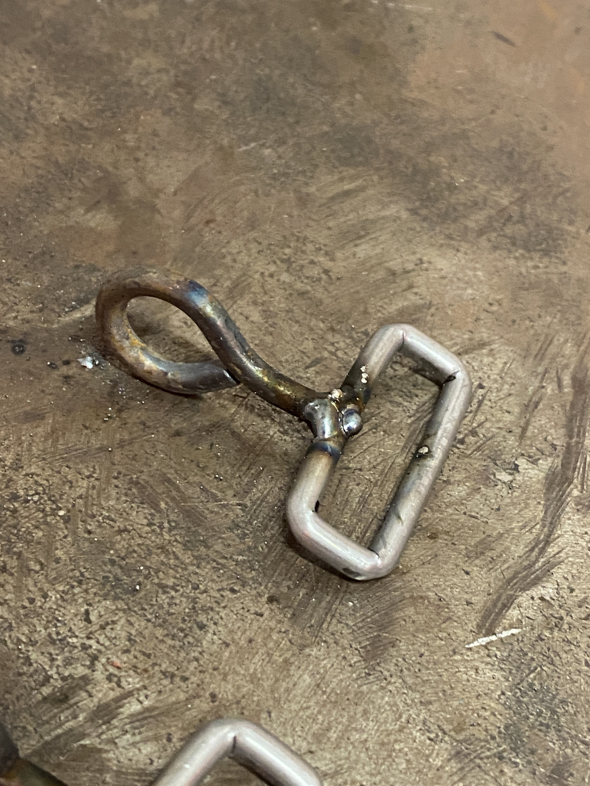
To ensure that the piece was kept a consistent design language between the back and front of the piece, I want to design the claps using the same sized forged links. I think that meshing these together and using forged hooks and leather straps will be the cleanest and harmonious with the overall piece.
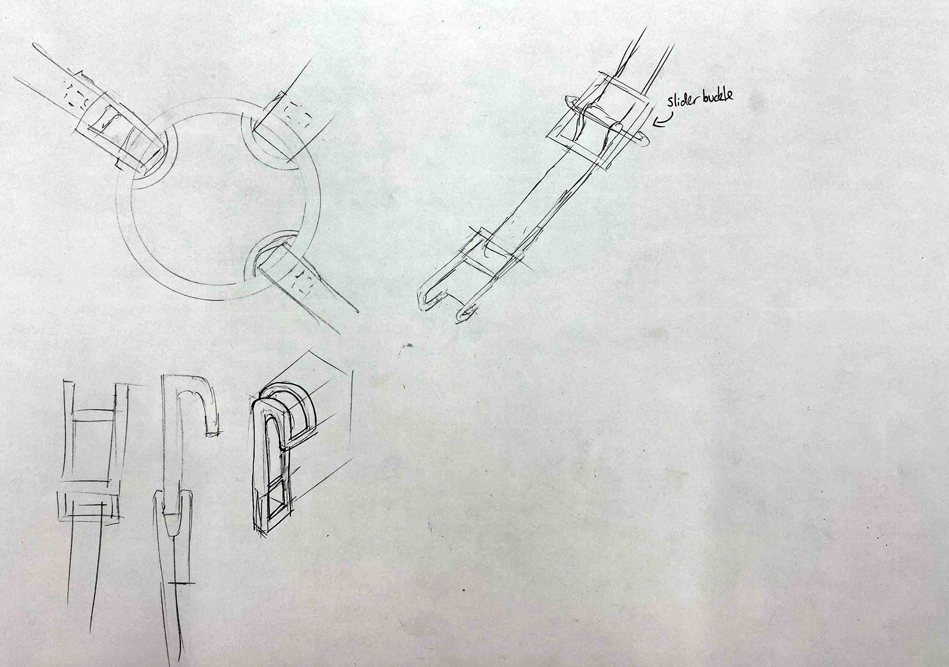
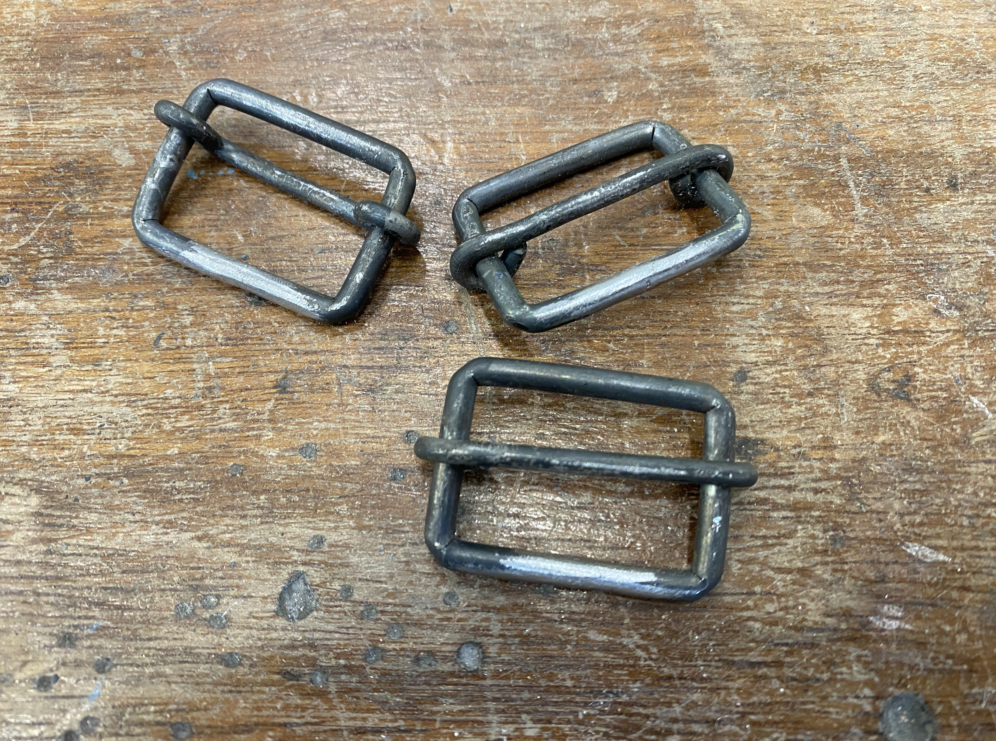
Reflecting on my previous pieces I realised that having adjustability to the strap length is important for a comfortable fit. Therefore, adding in a slider buckle will allow the stap length to be adjusted by threading more material through.
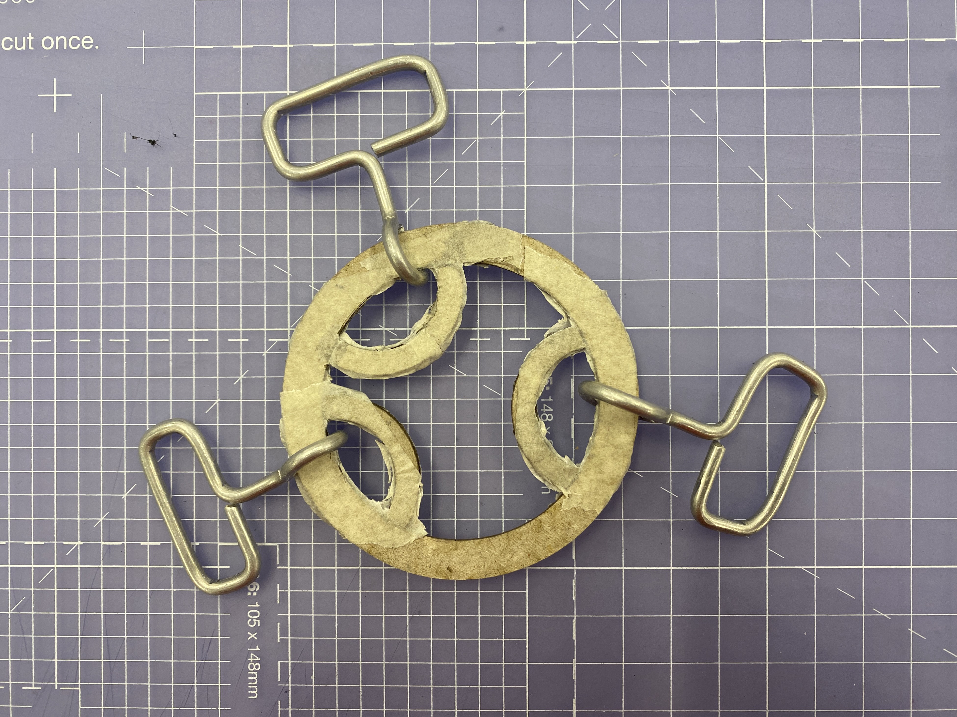

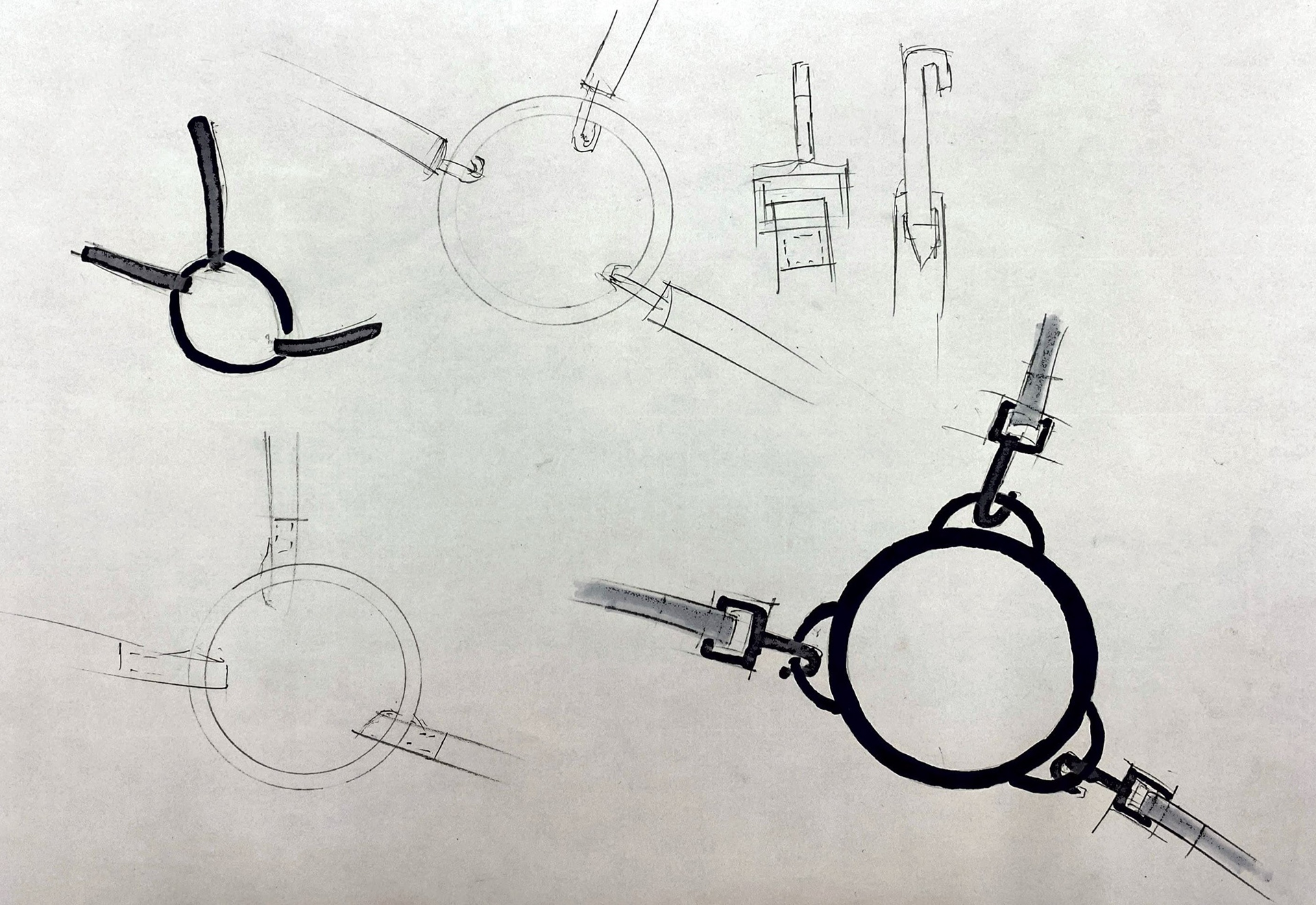
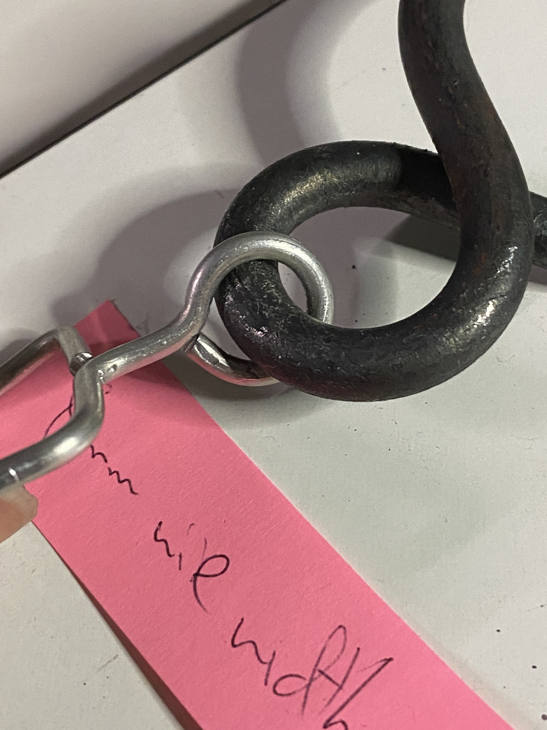
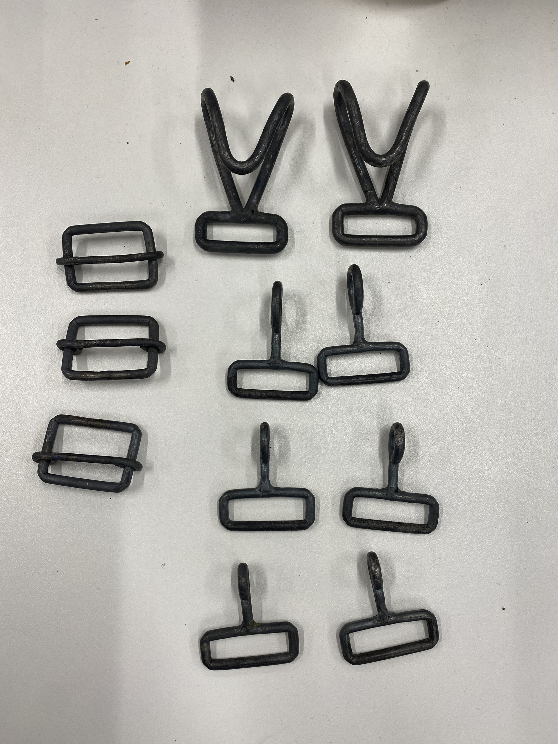
I started by designing the lower clasping mechanism, focusing on the positioning of each buckle so that the strap would run along the taped-out guidelines. The pictures above show the closed buckles attached to the clasp. However, one of these needs to be detachable to allow the piece to be taken on and off. I decided that the right buckle on the clasp mechanisms should be detachable. This would mean the left arm would be placed through the straps like a shirt. The right side of the piece would then need to be hooked together to complete the piece and hold it onto the body.
This style of attaching the piece will require the assistance of others to put on and take off. This is necessary for the aesthetic of the piece and is consistent with the wearability of traditional armour. I don't know how this will affect the narrative of being dependent on others to wear the piece. It may take away from the empowerment of suiting up into the piece as you are reliant on the assistance of others.
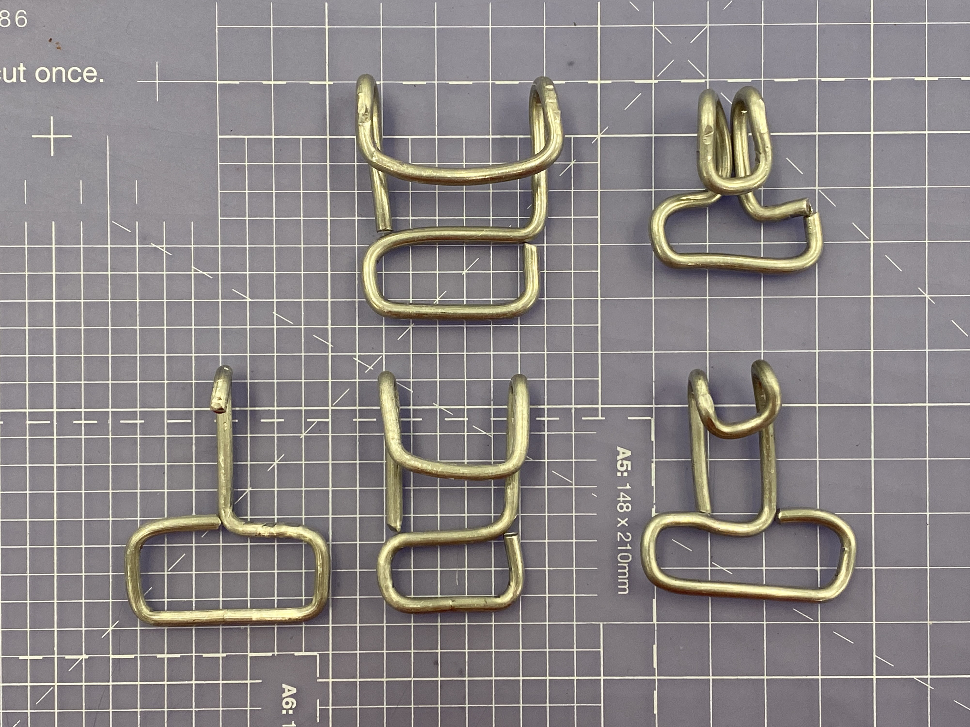
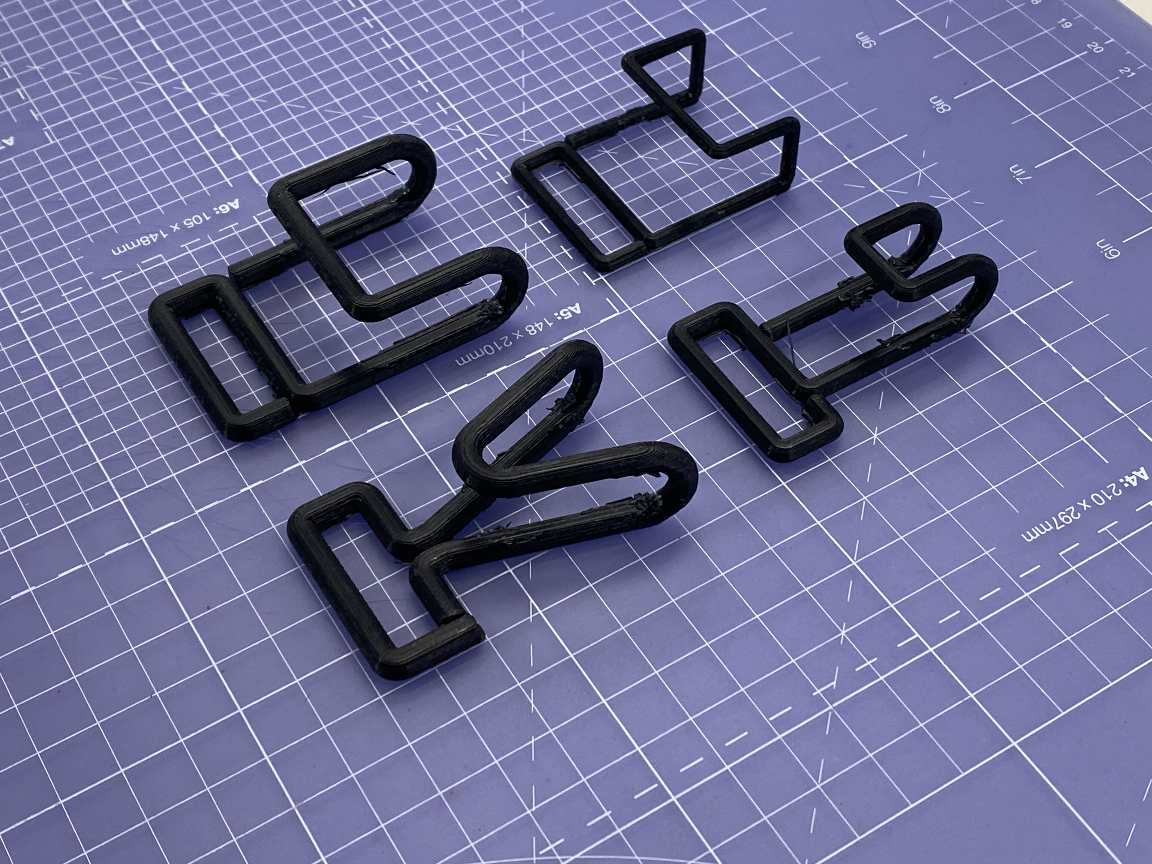
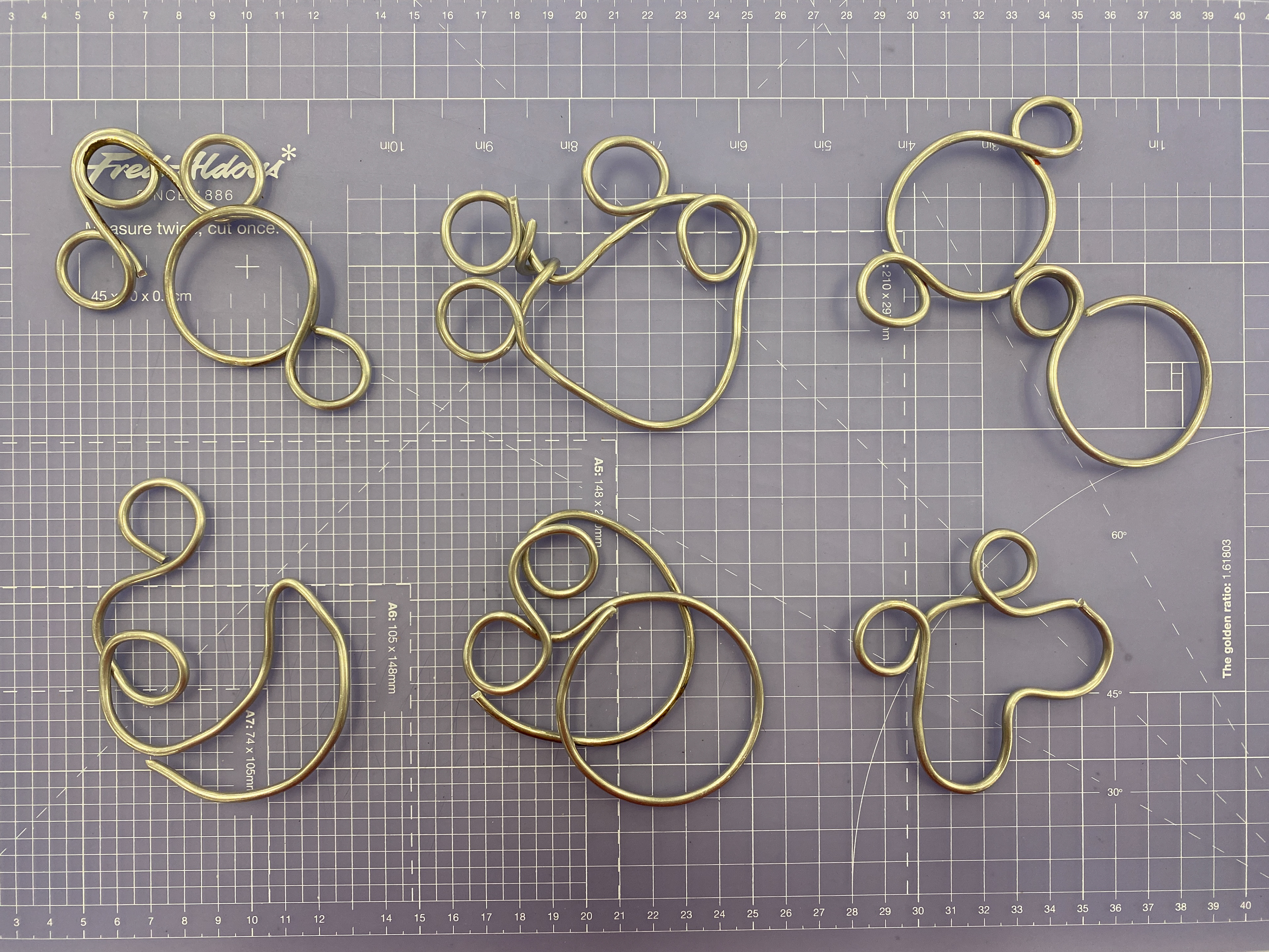
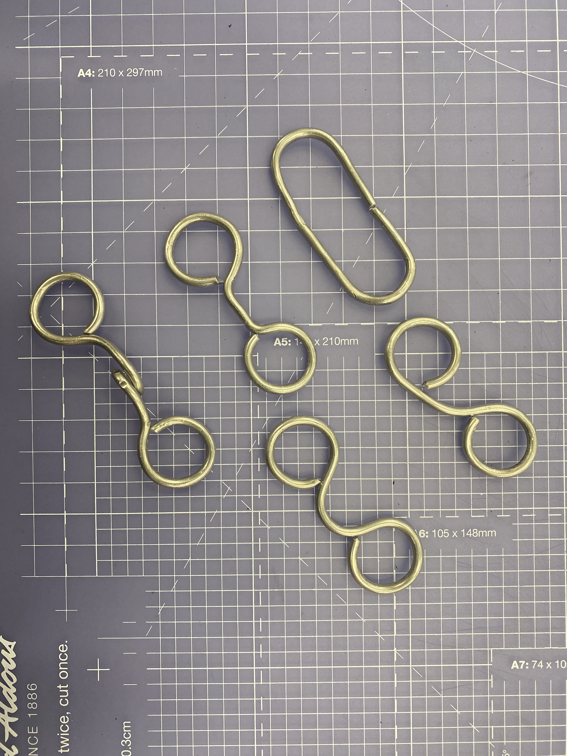
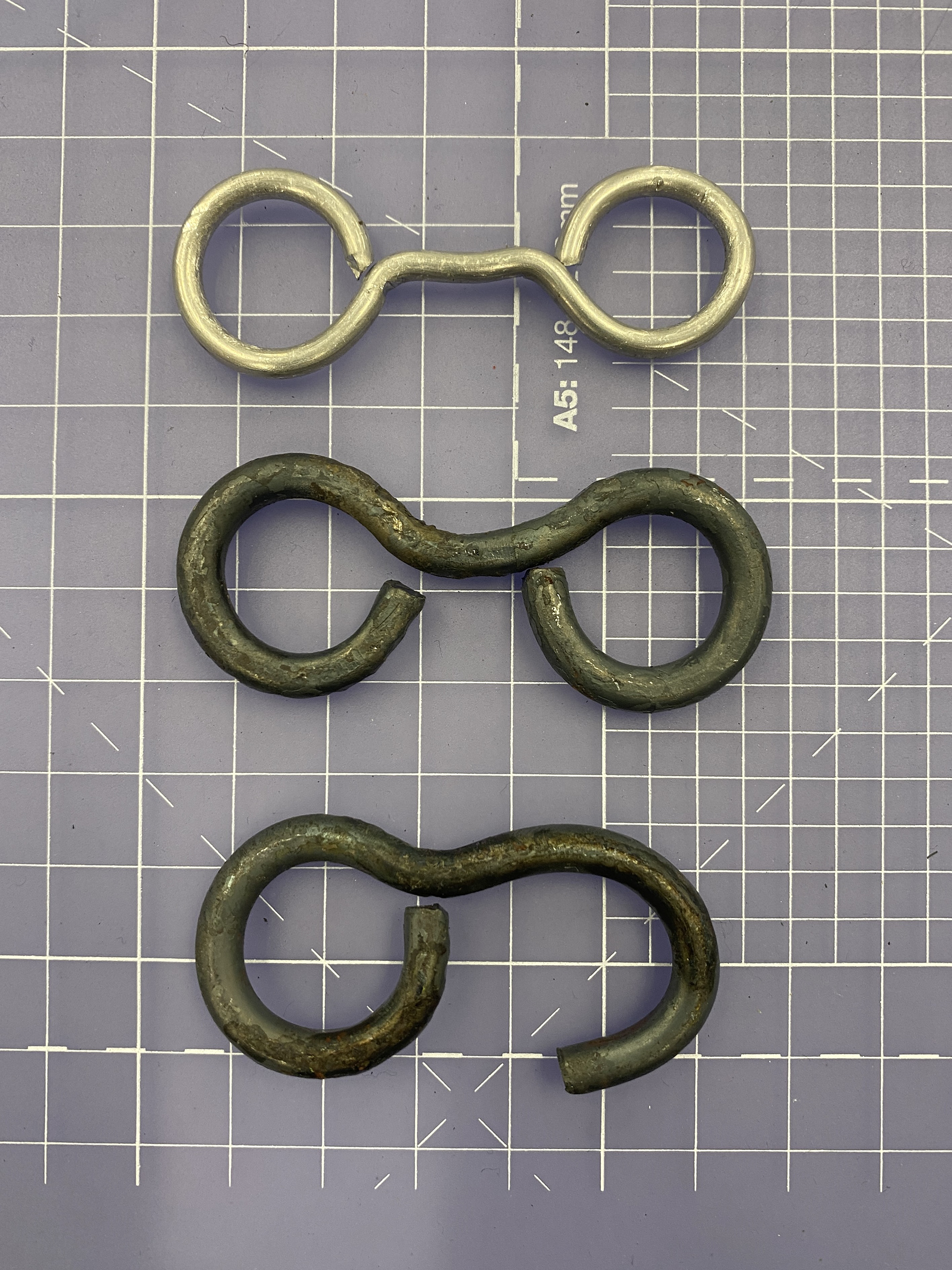
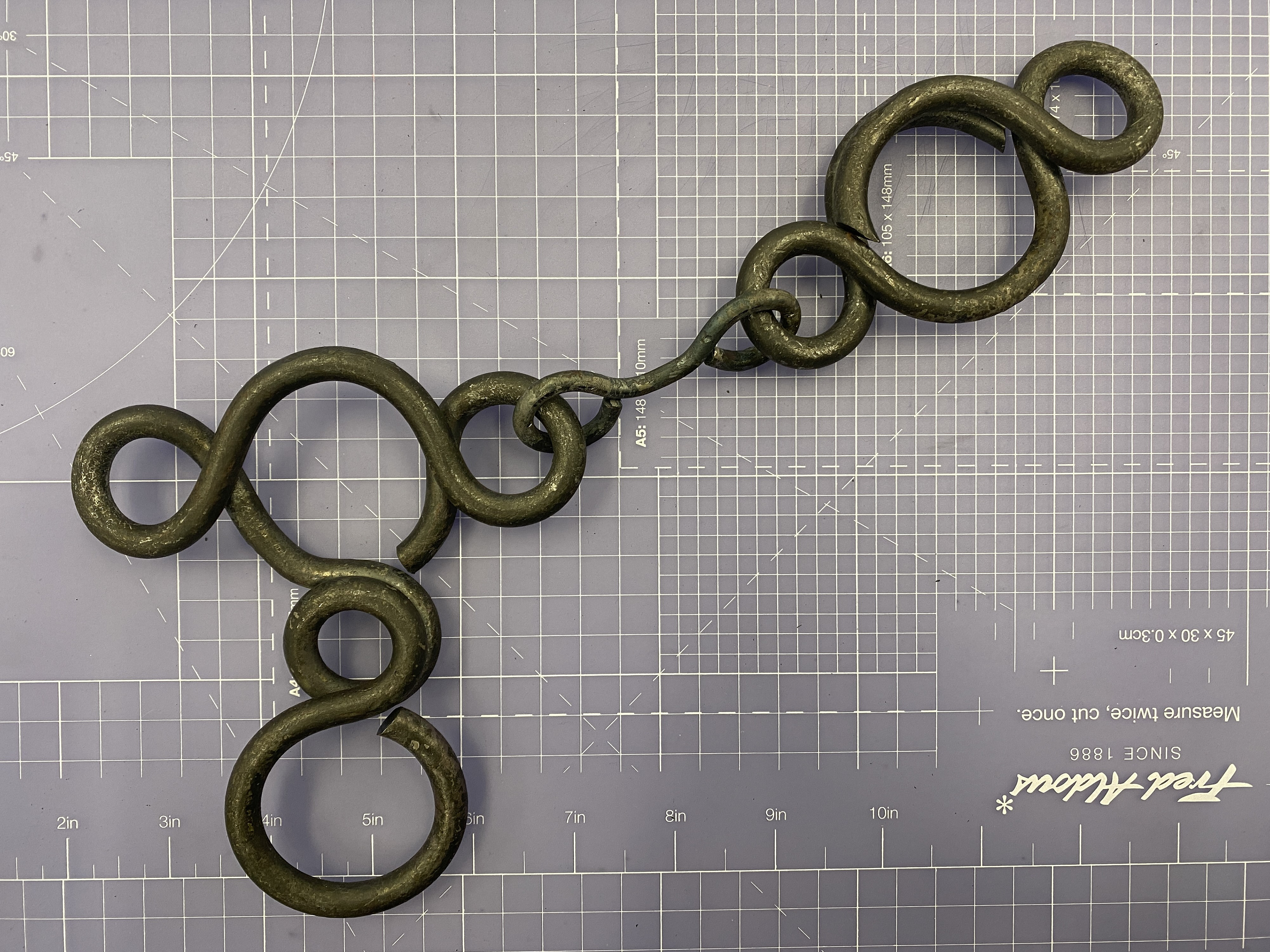
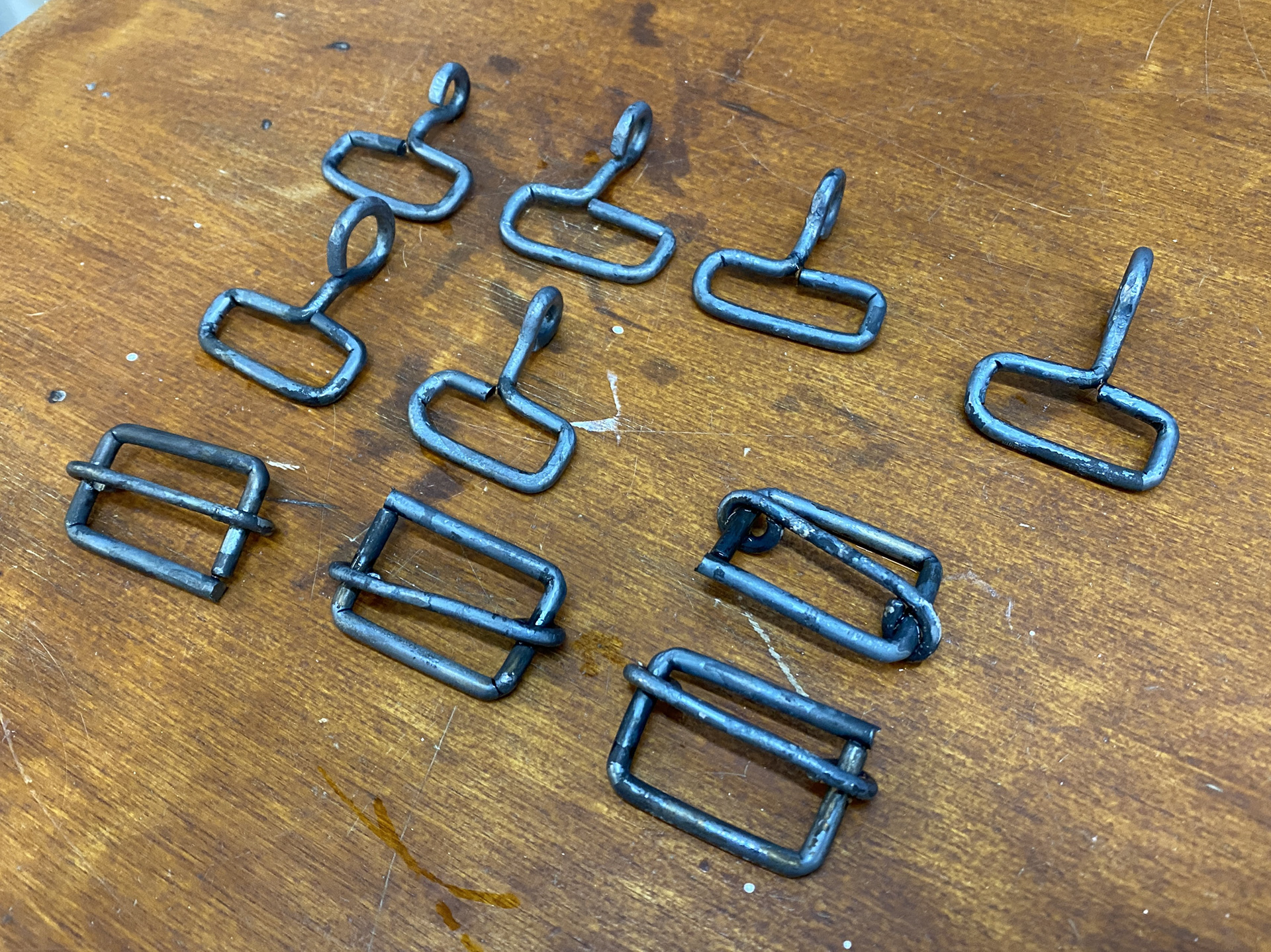
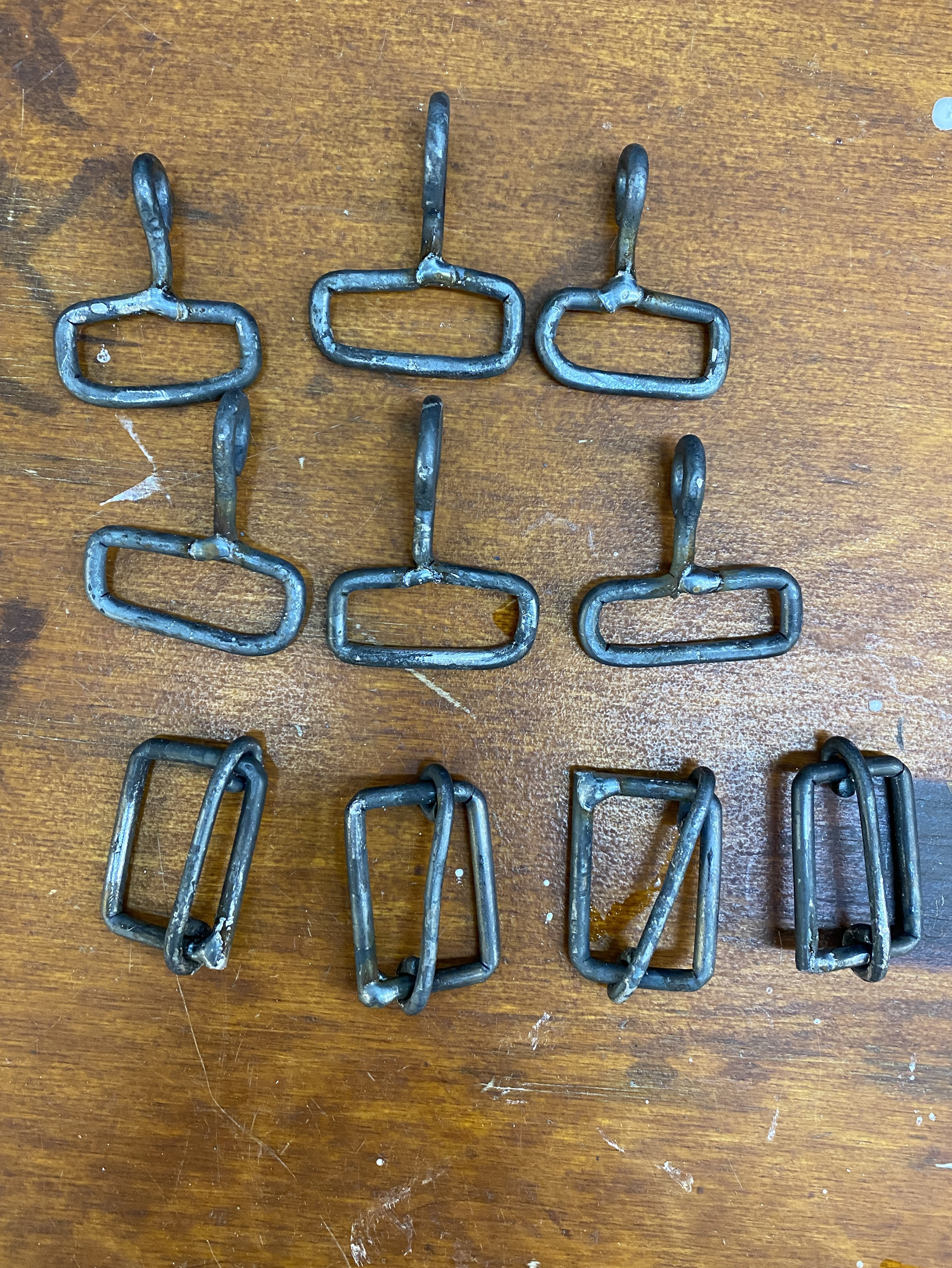
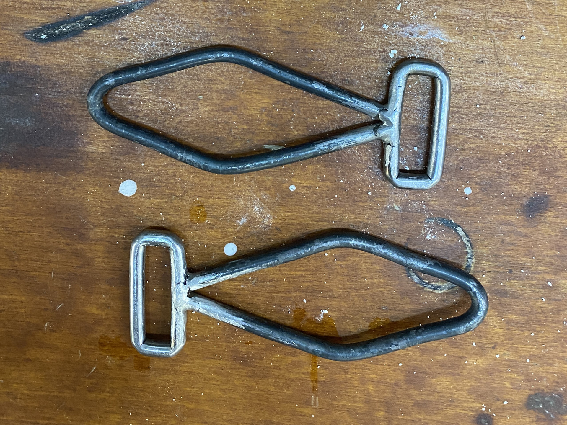
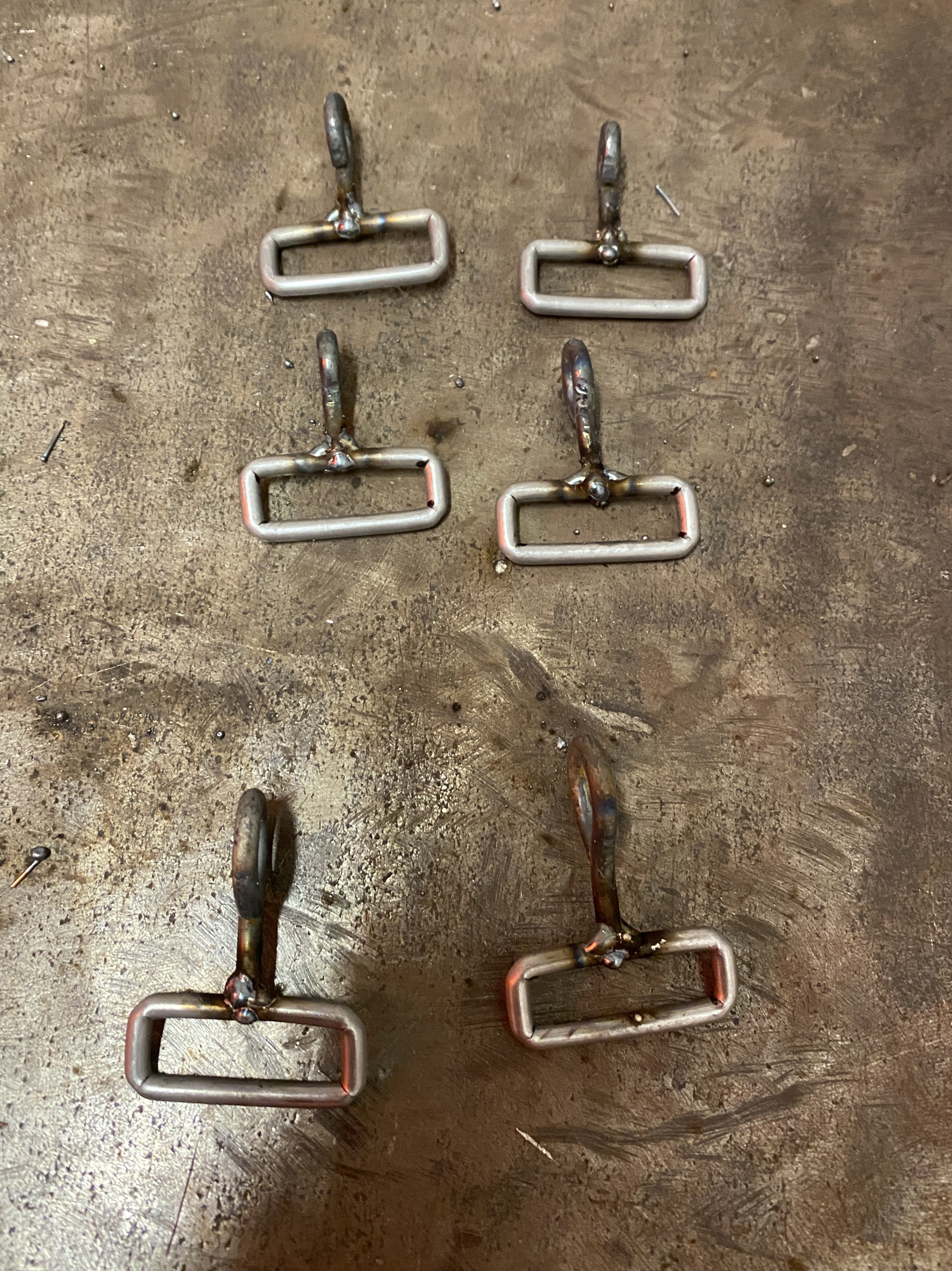
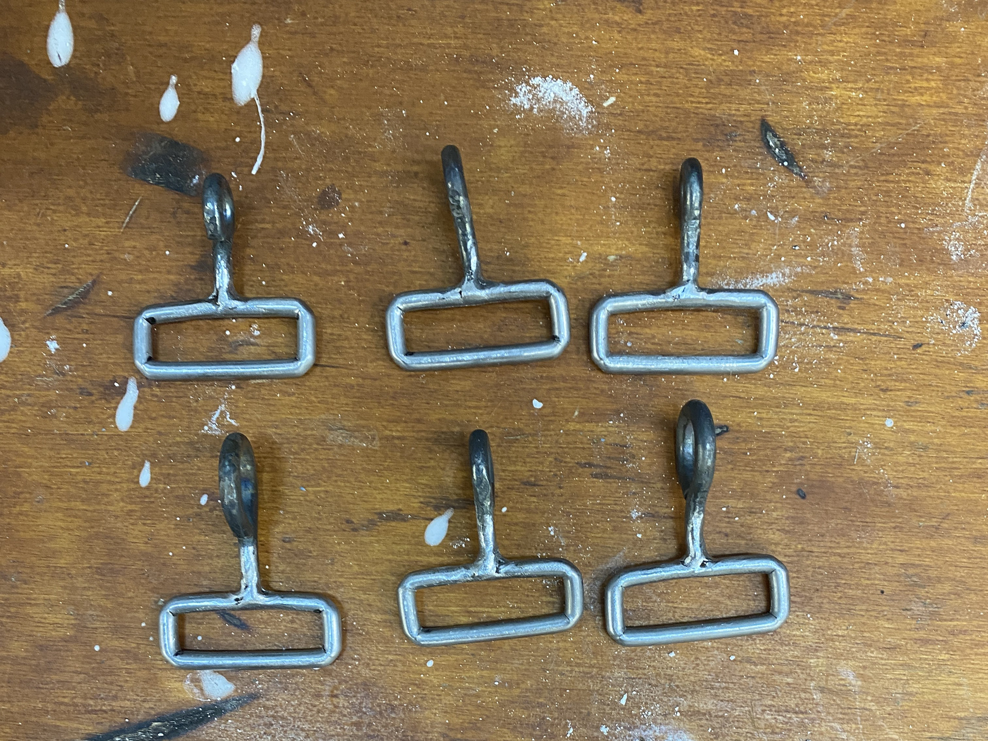
The photo on the left shows a series of different designs looking at connecting different sized links together for two of the clasps to permanently be connected and one to hook on and off. One of my main struggles was trying to not create a composition that resembled a logo or symbol that had other connotations.
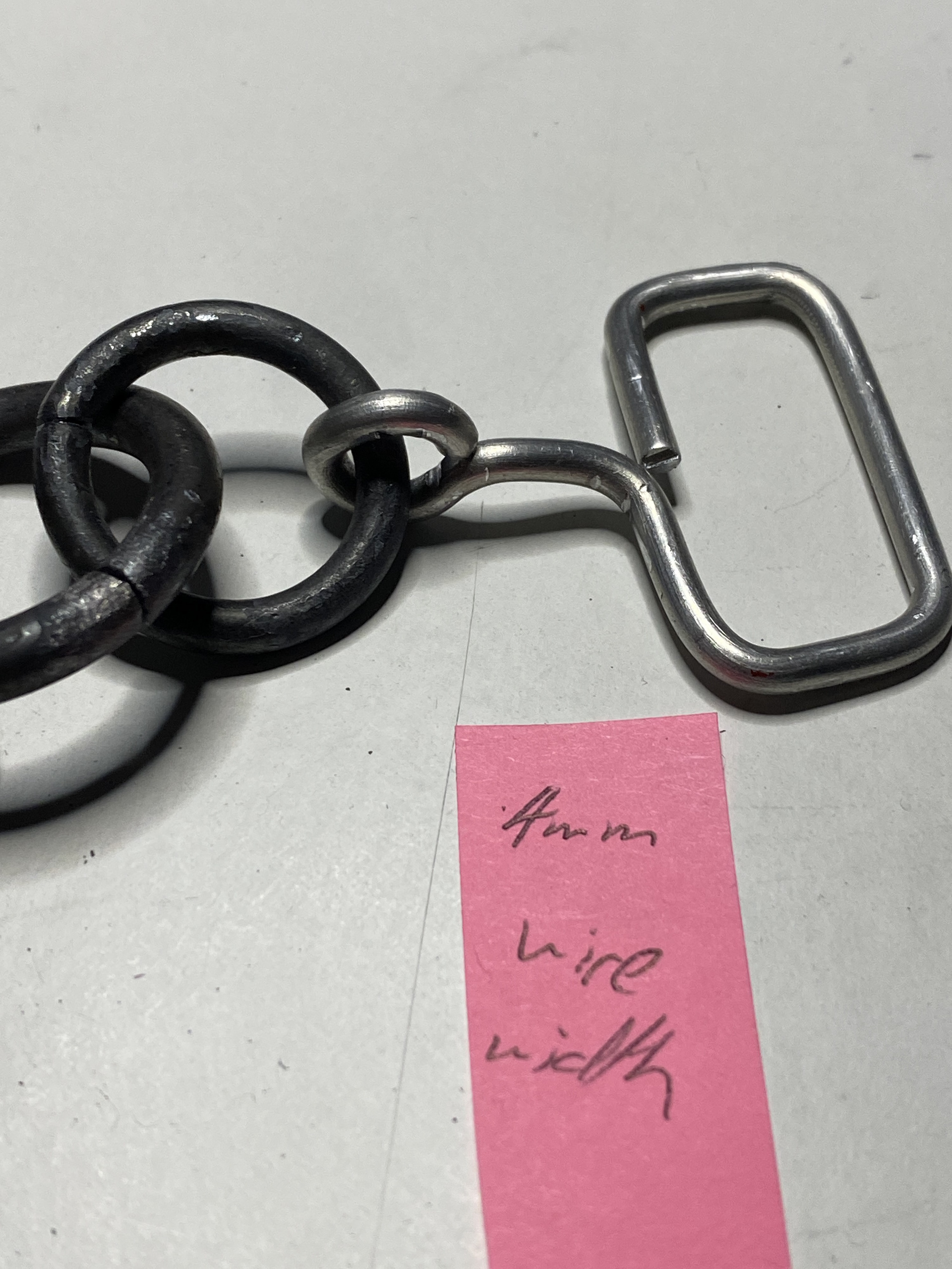
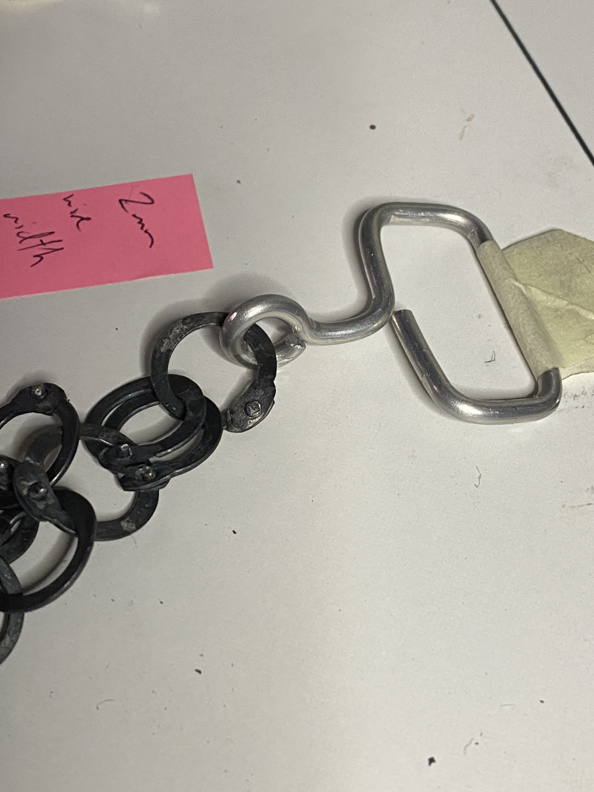
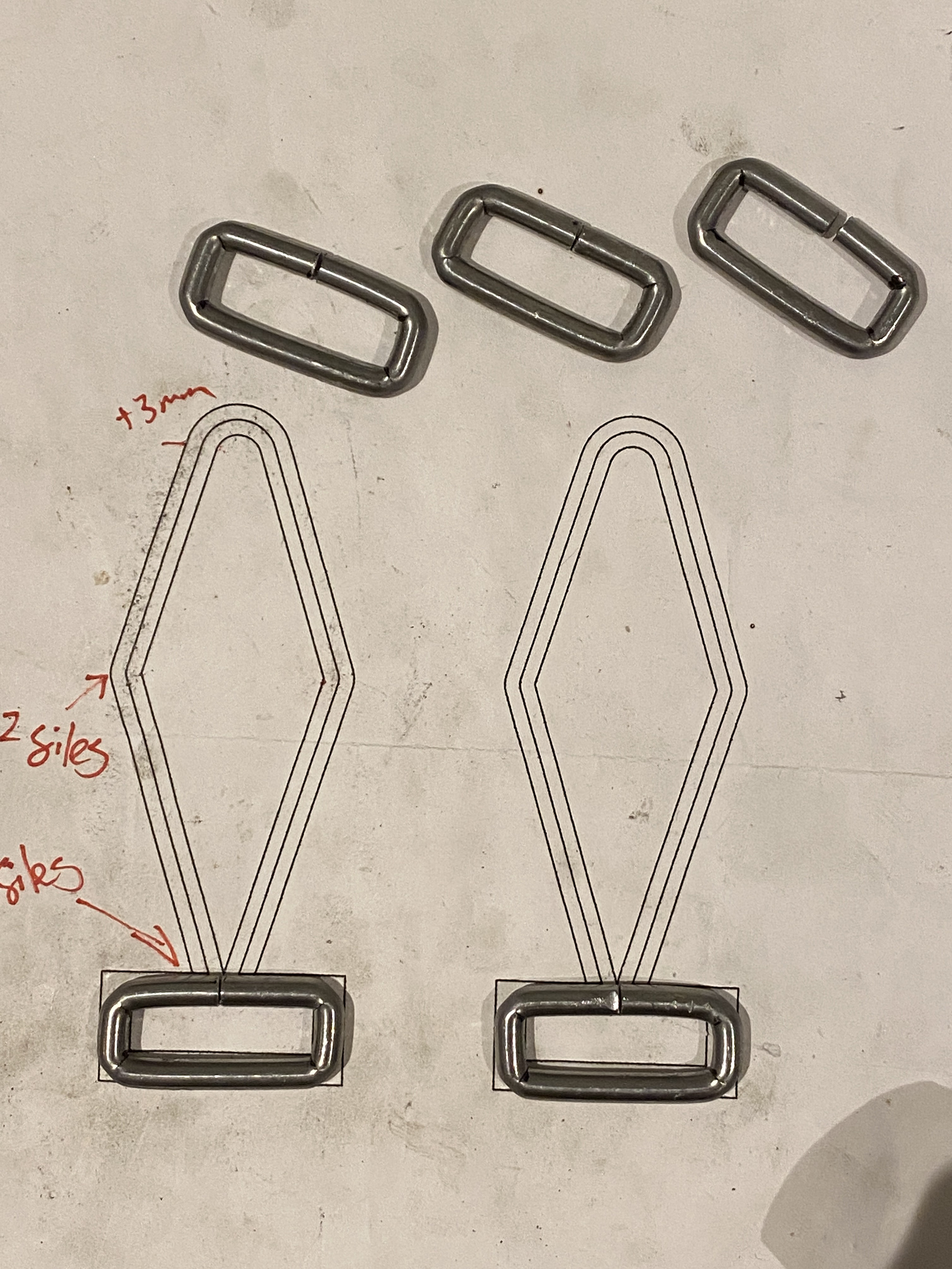
The buckles show different sizes and ways of manufacturing from one continuous piece of wire. I think the largest rectangular design is the most successful as it feels sturdier when hooking it together. Additionally, this will reduce the amount the strap slides around.
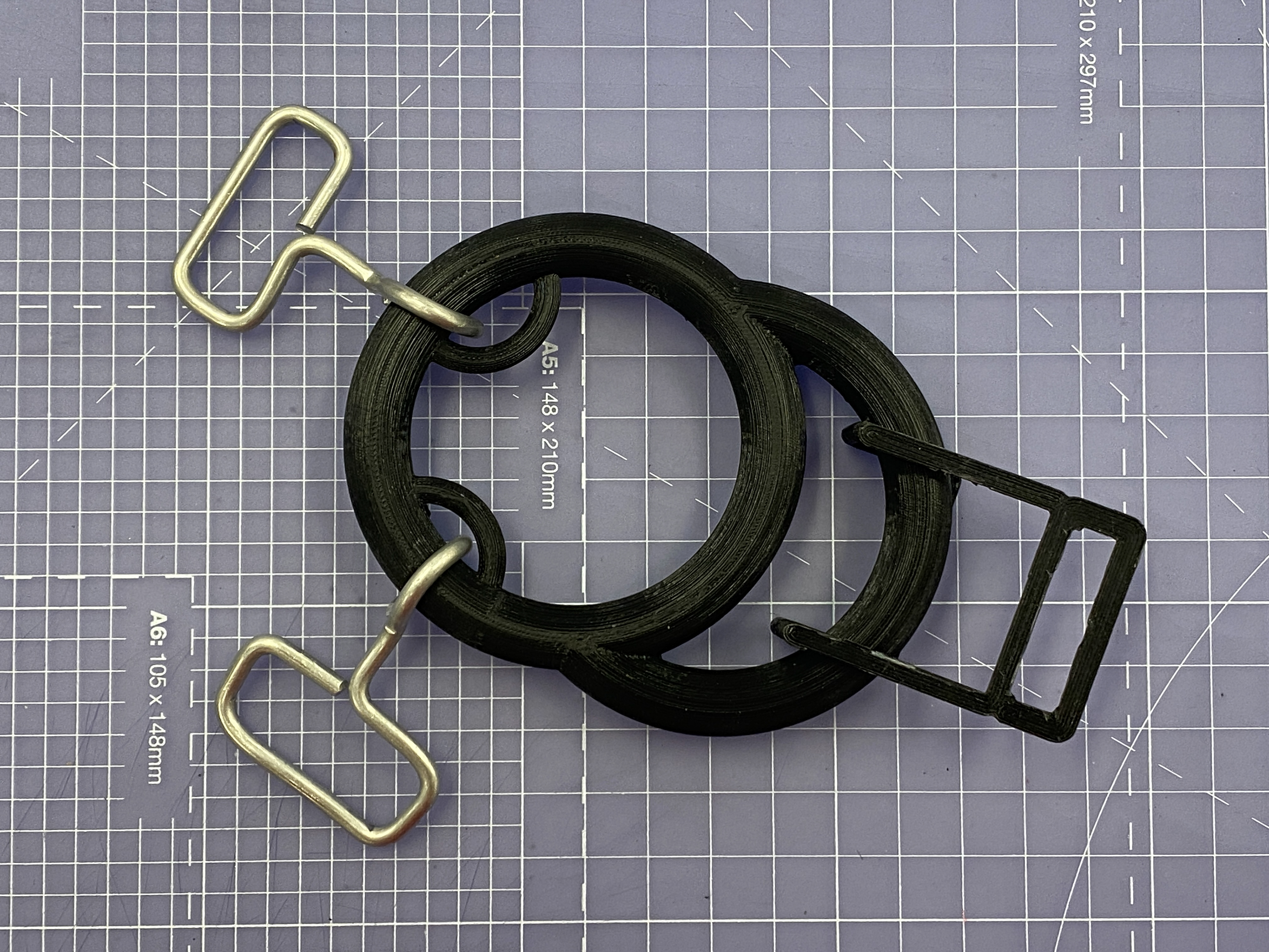
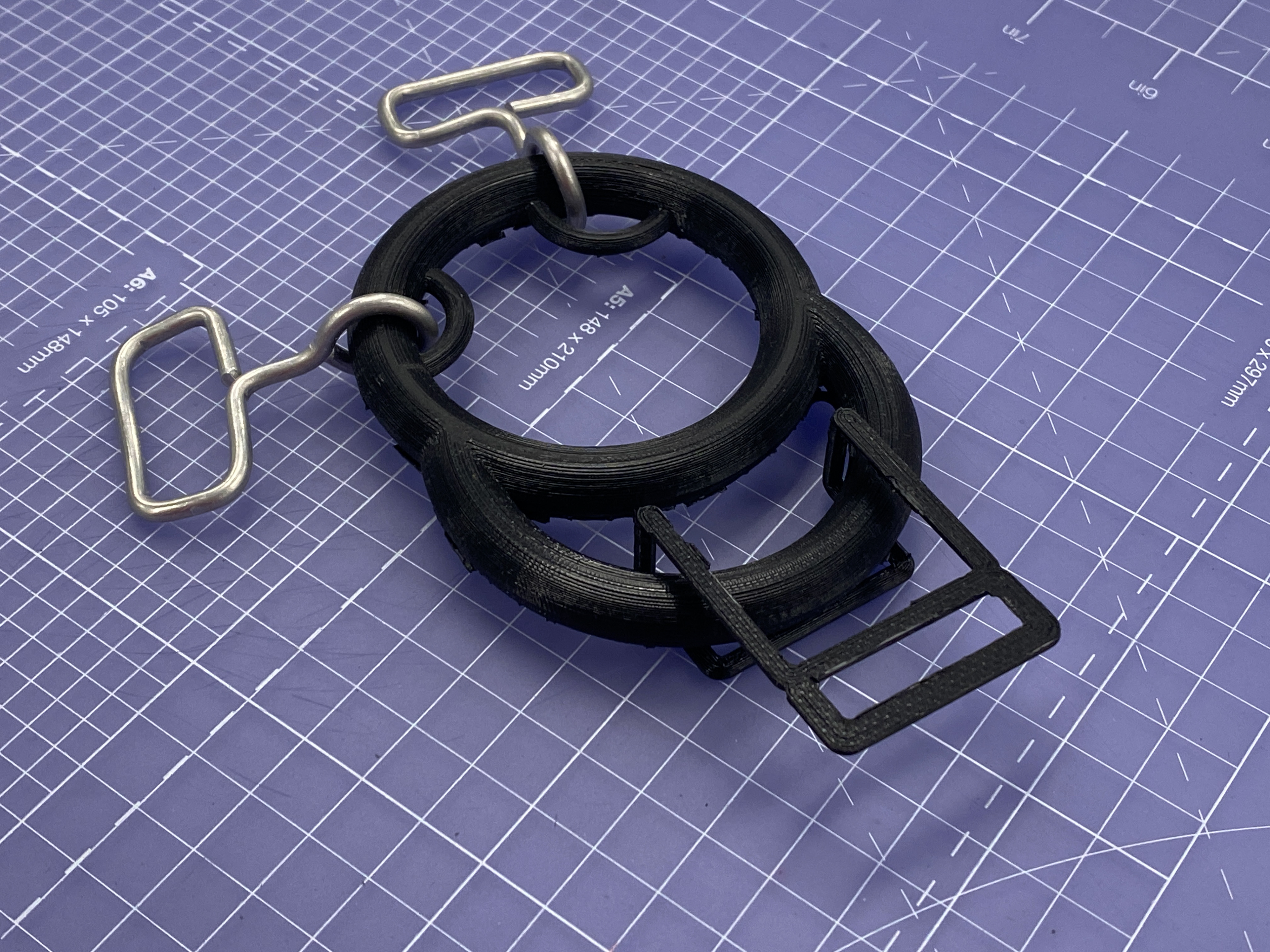
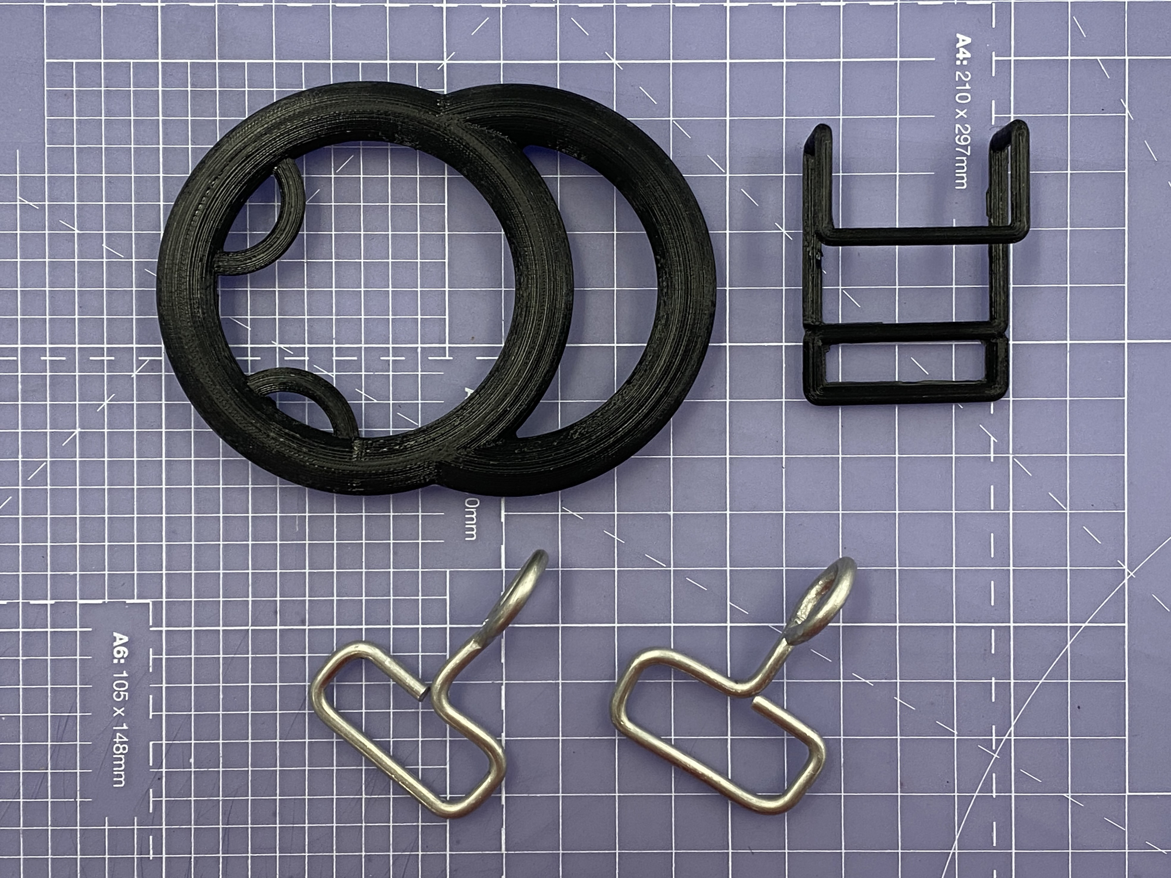
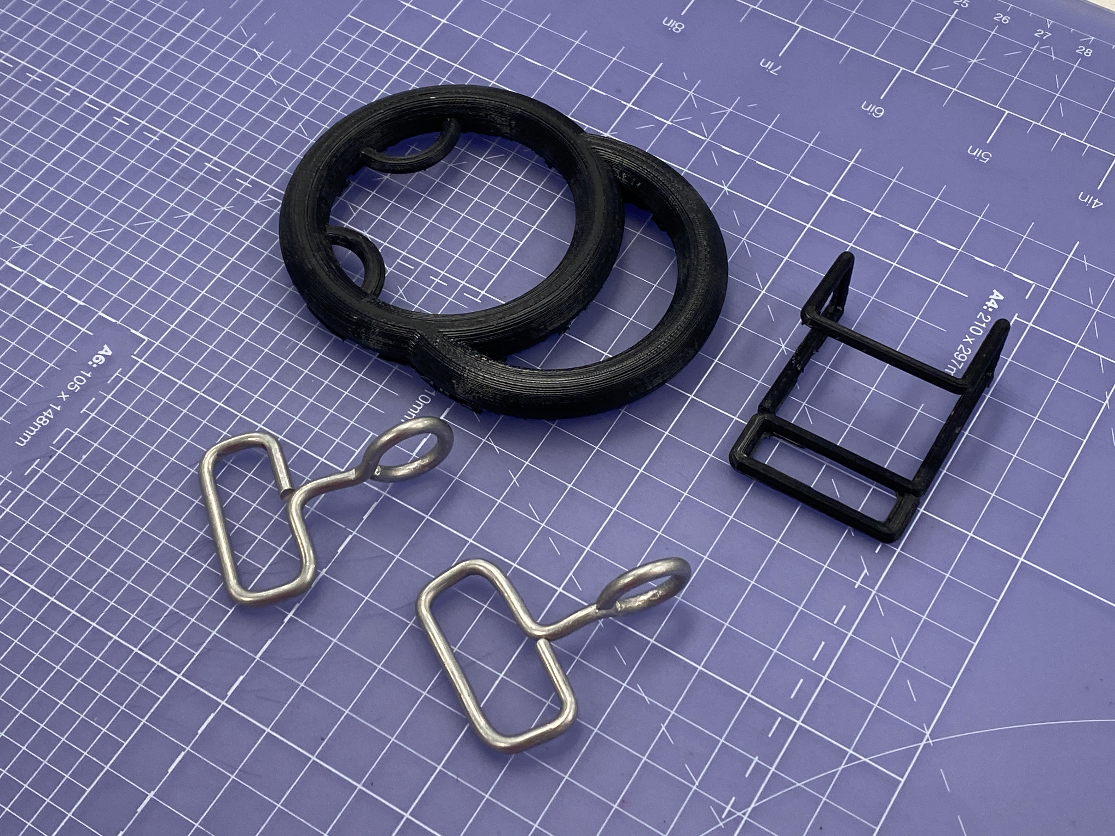
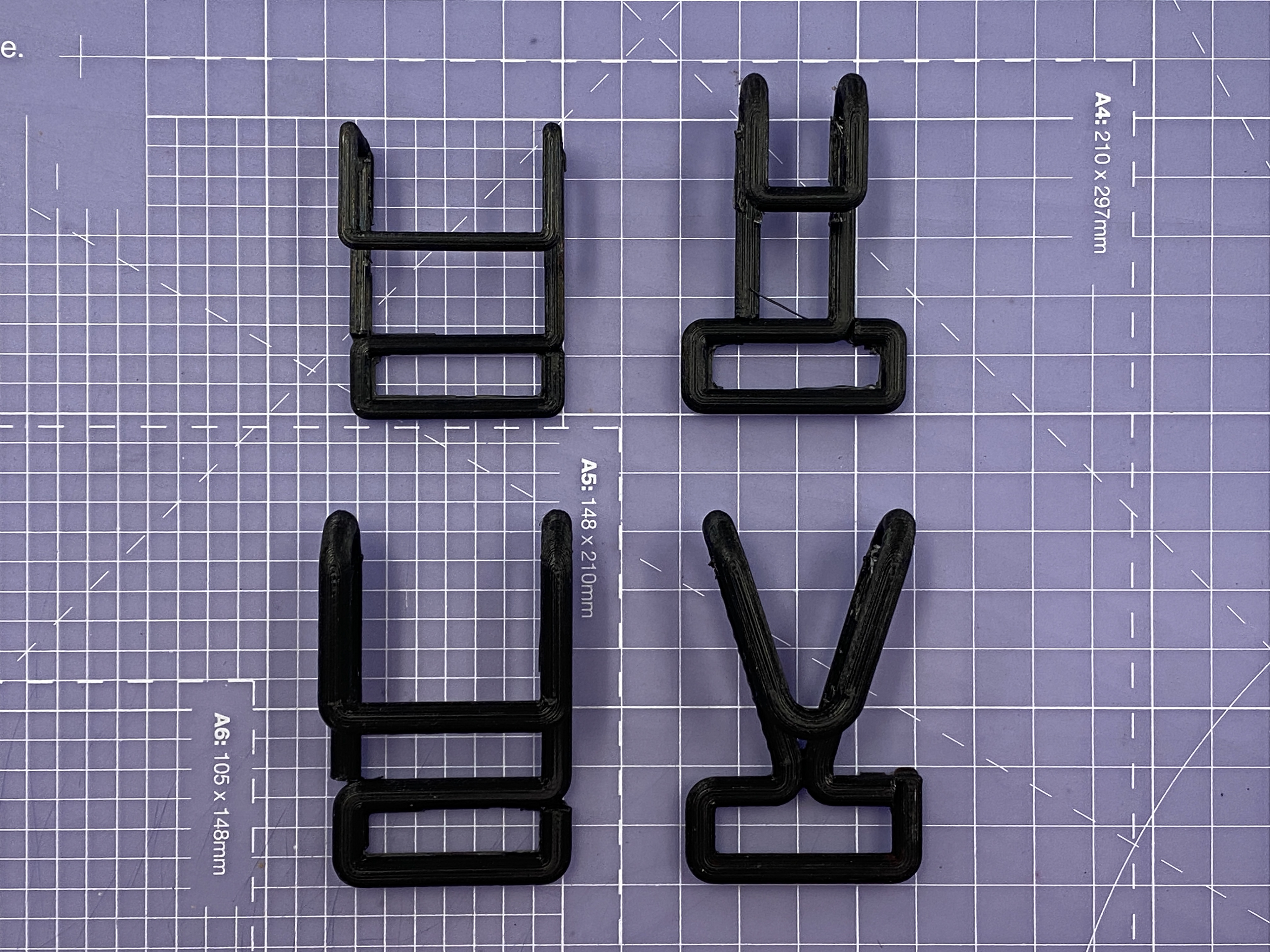
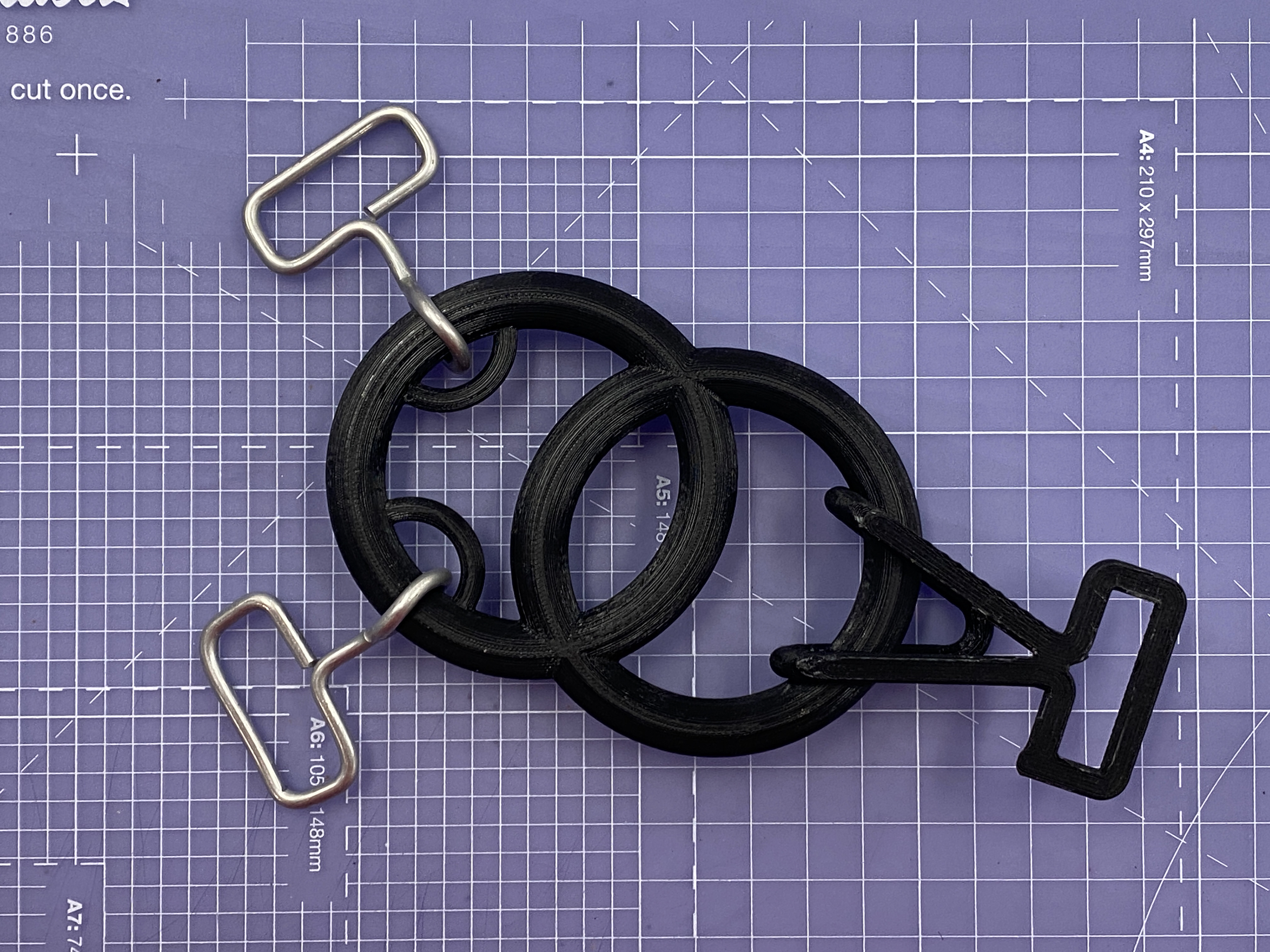
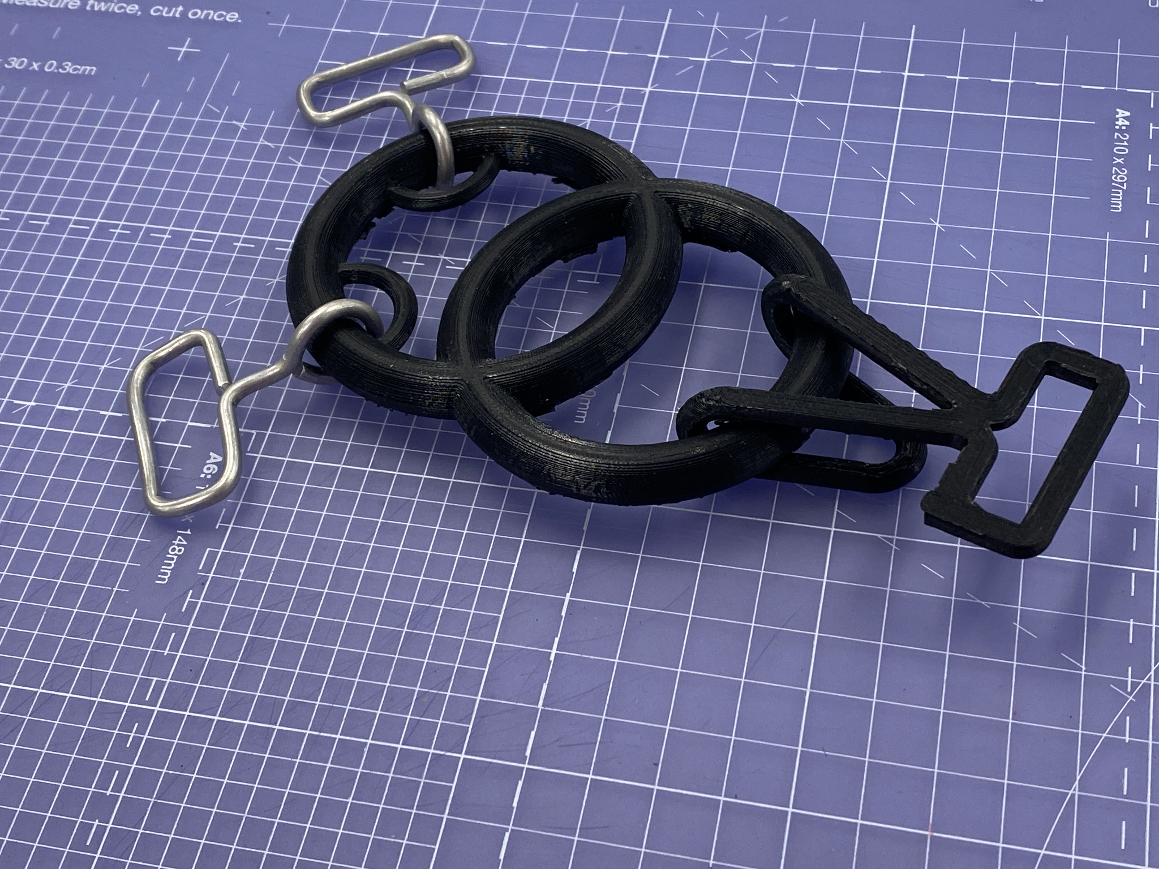
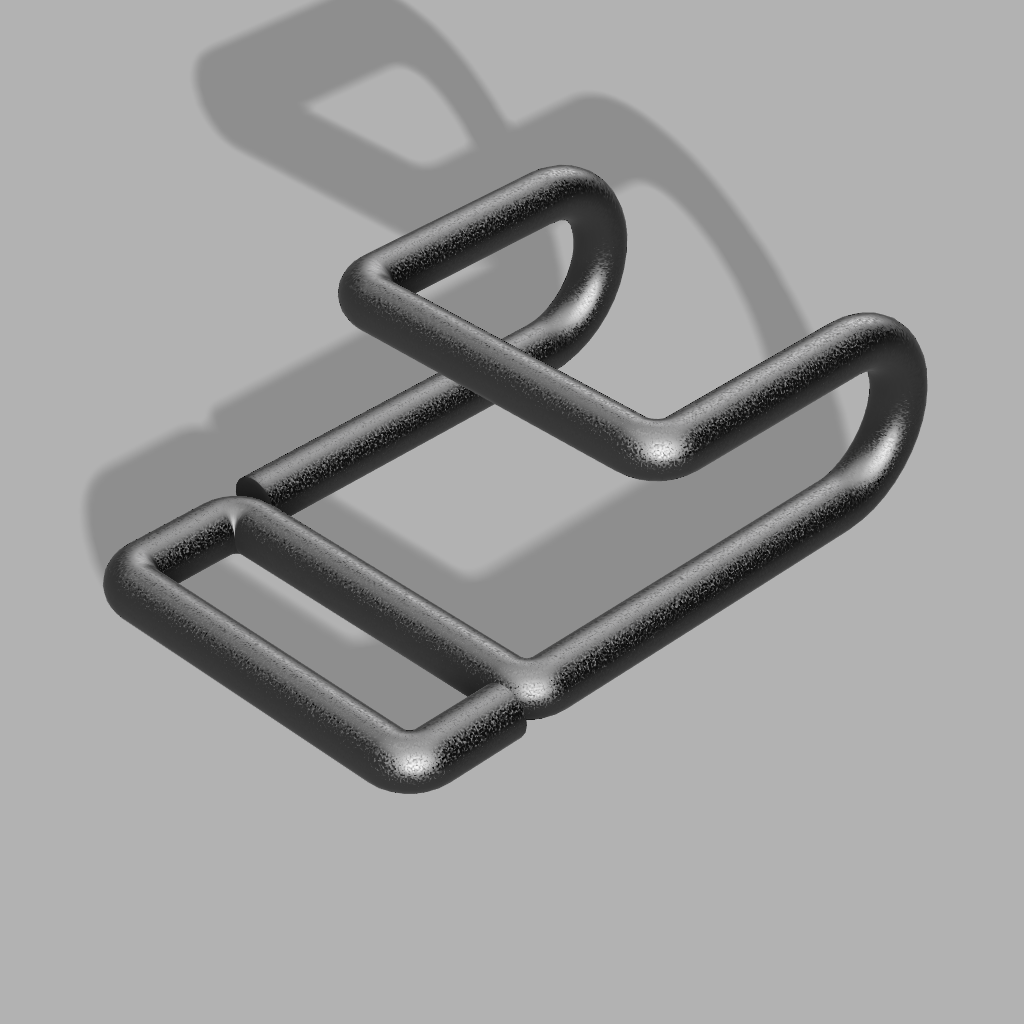
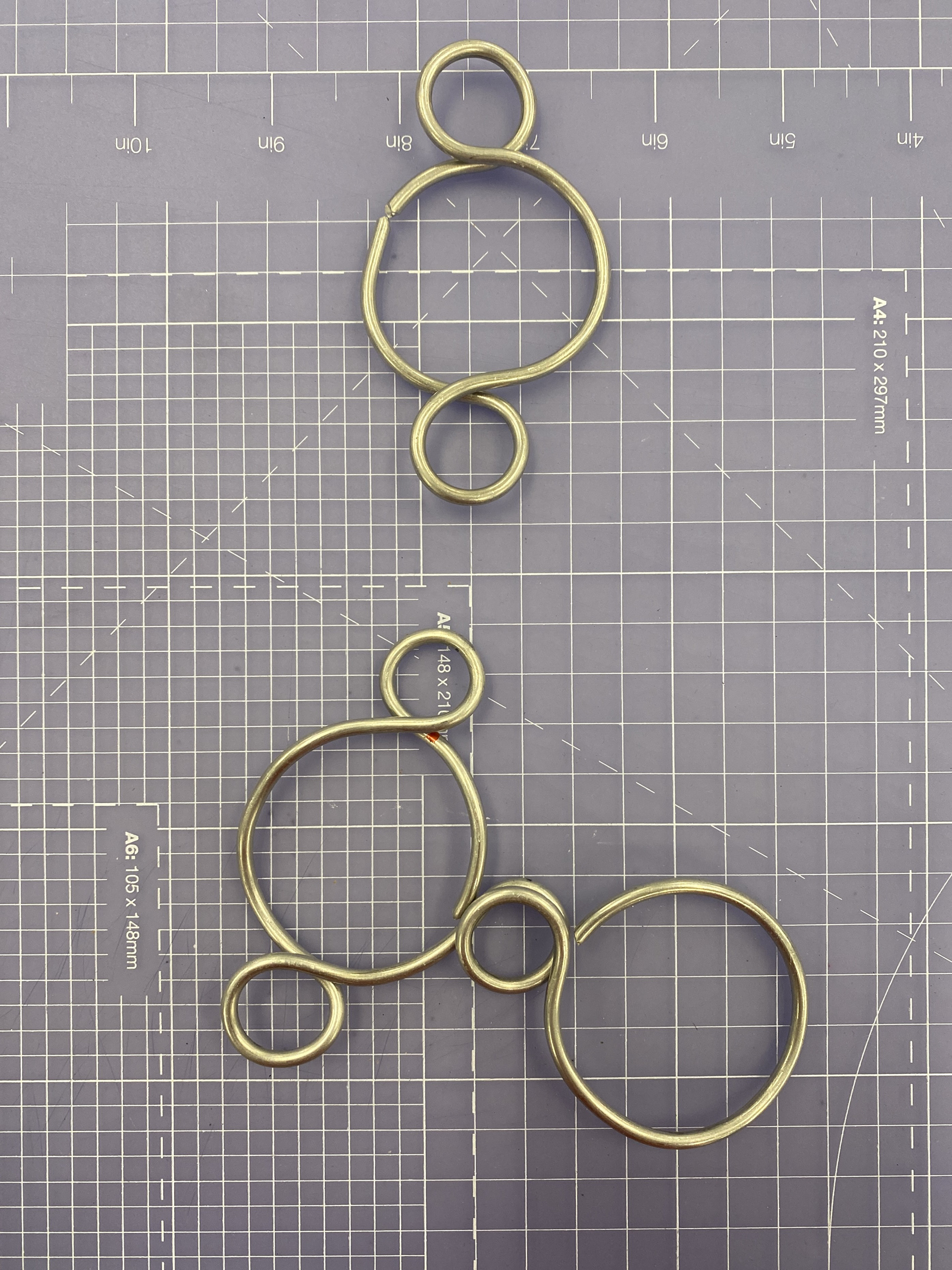
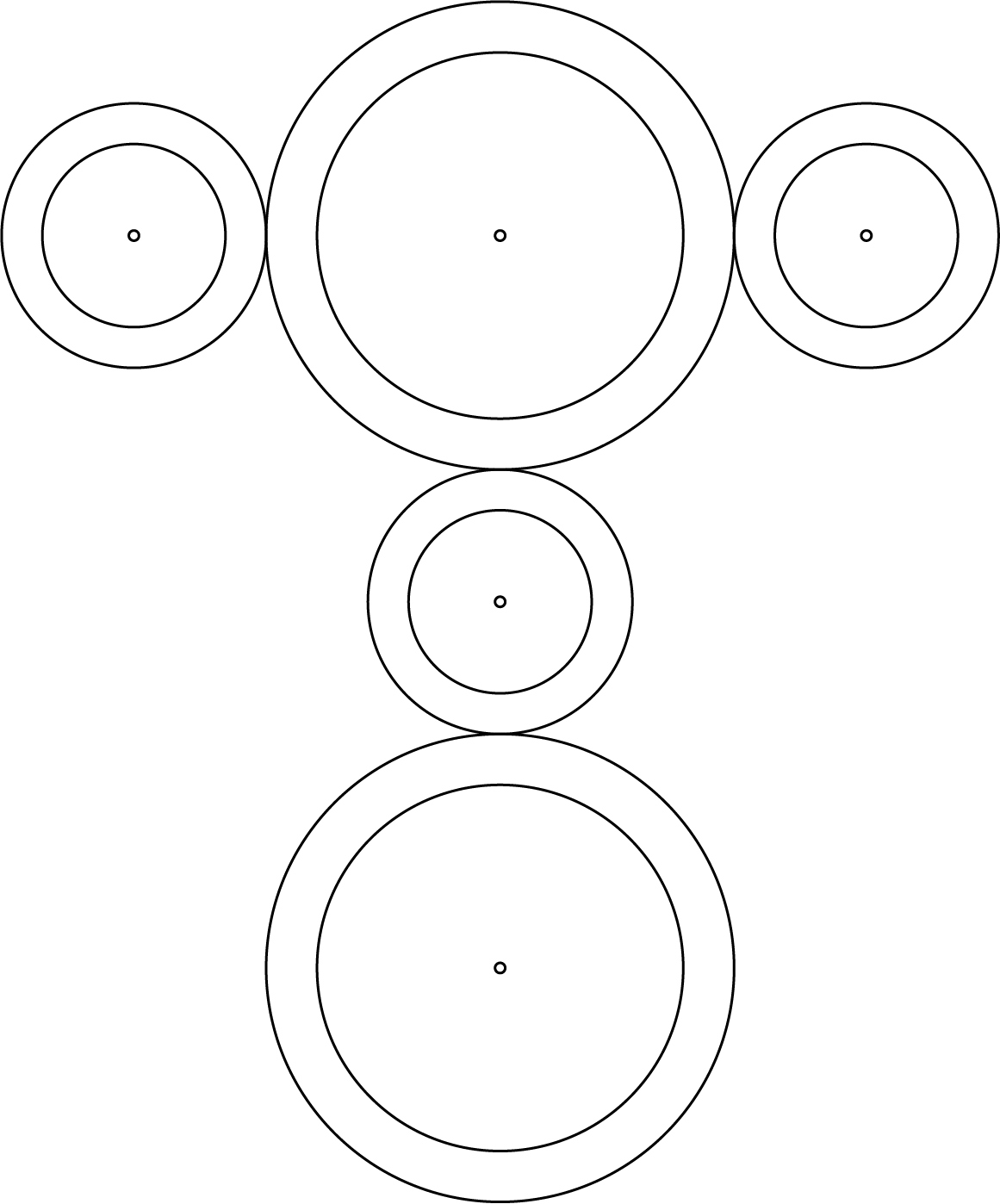
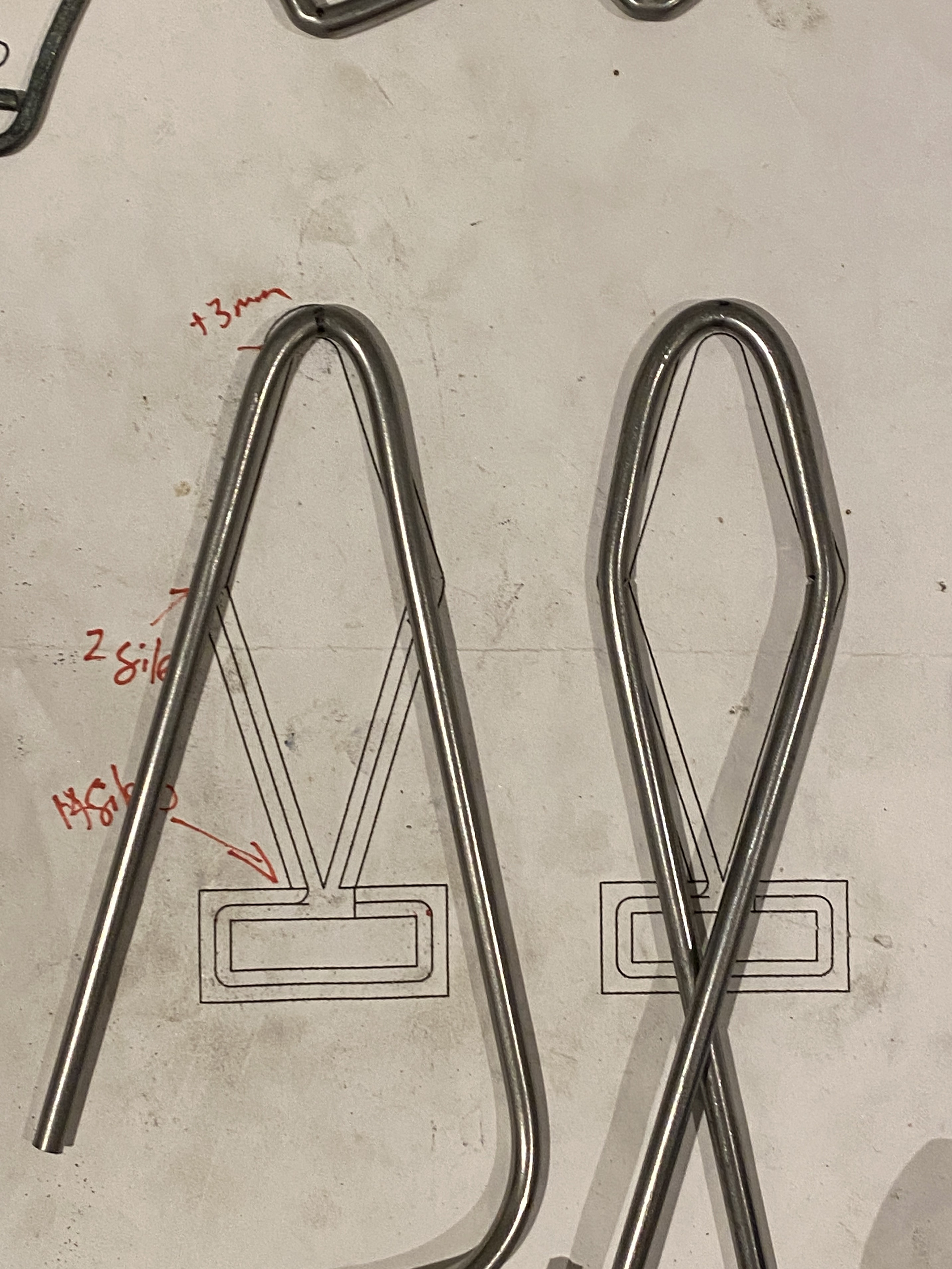
I chose the design above to develop further as it didn't resemble any other symbols and echoed the interlocking nature of the chain. I created a CAD design and 3D printed it to gain a better understanding of how the different components connected. Additionally, I wanted to look at how the larger rings would interact with the smaller ones in 3D as my cardboard tests couldn't showcase this. These links will be cut and welded together to make a strong and singular piece.
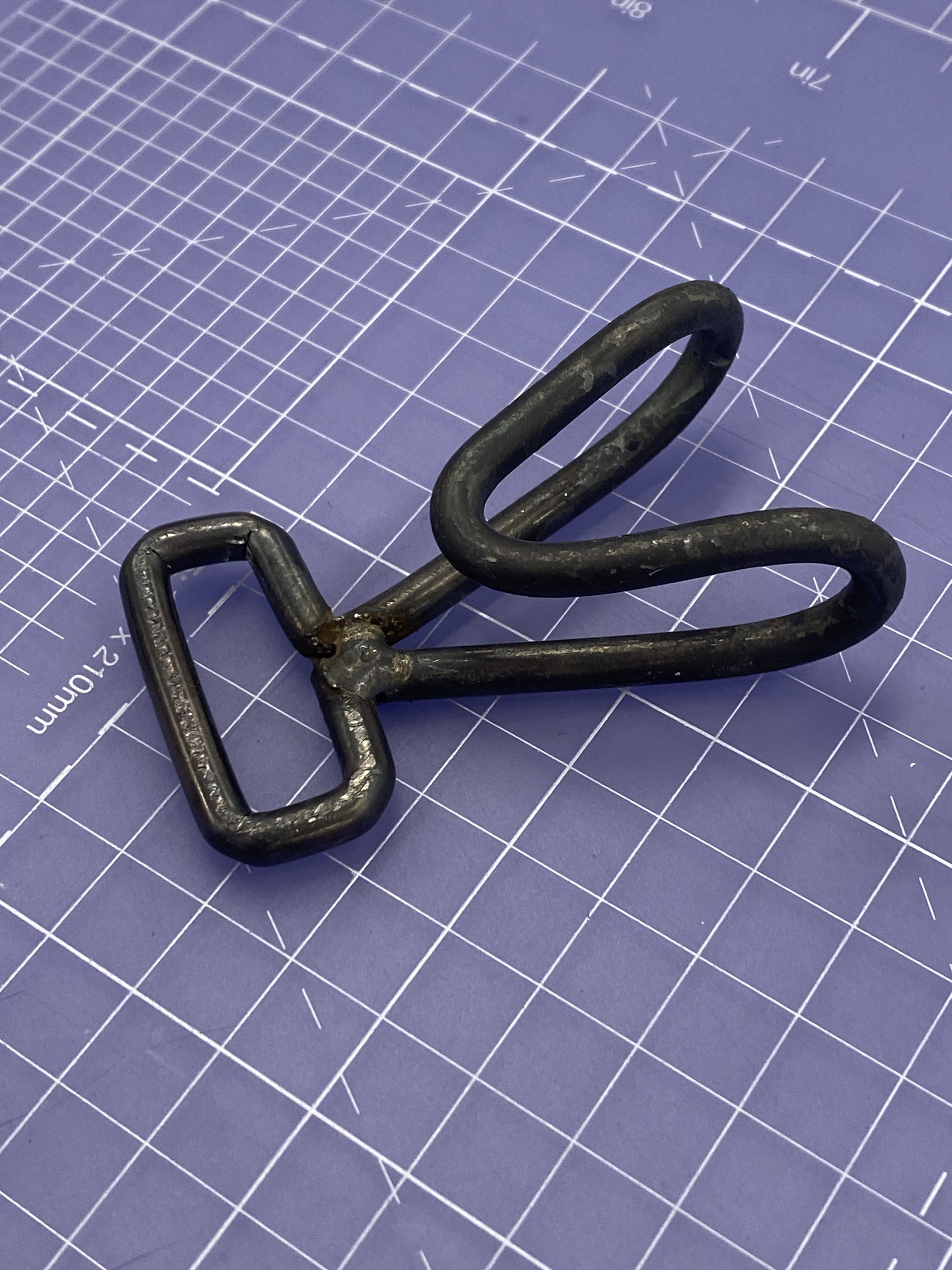
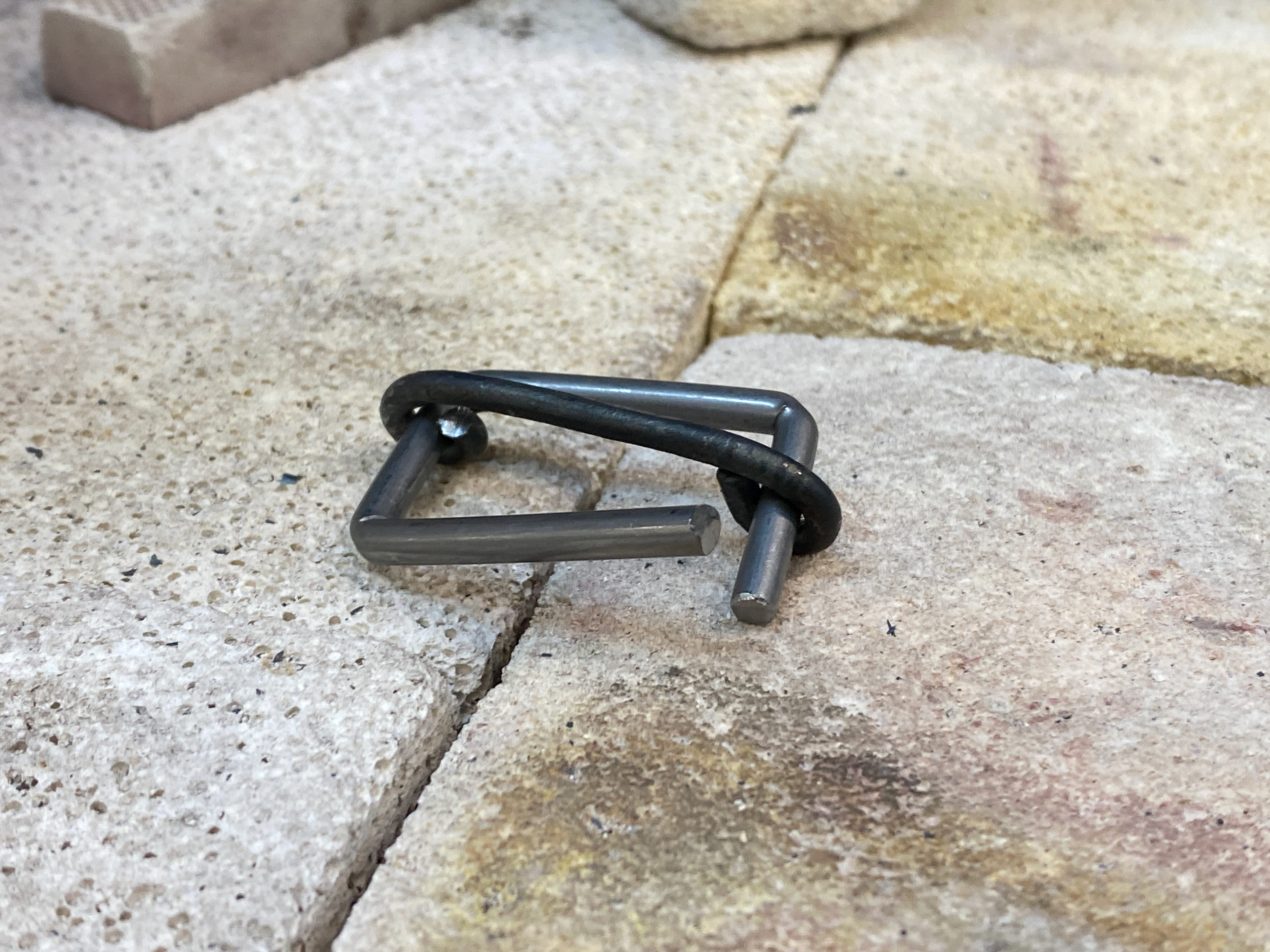
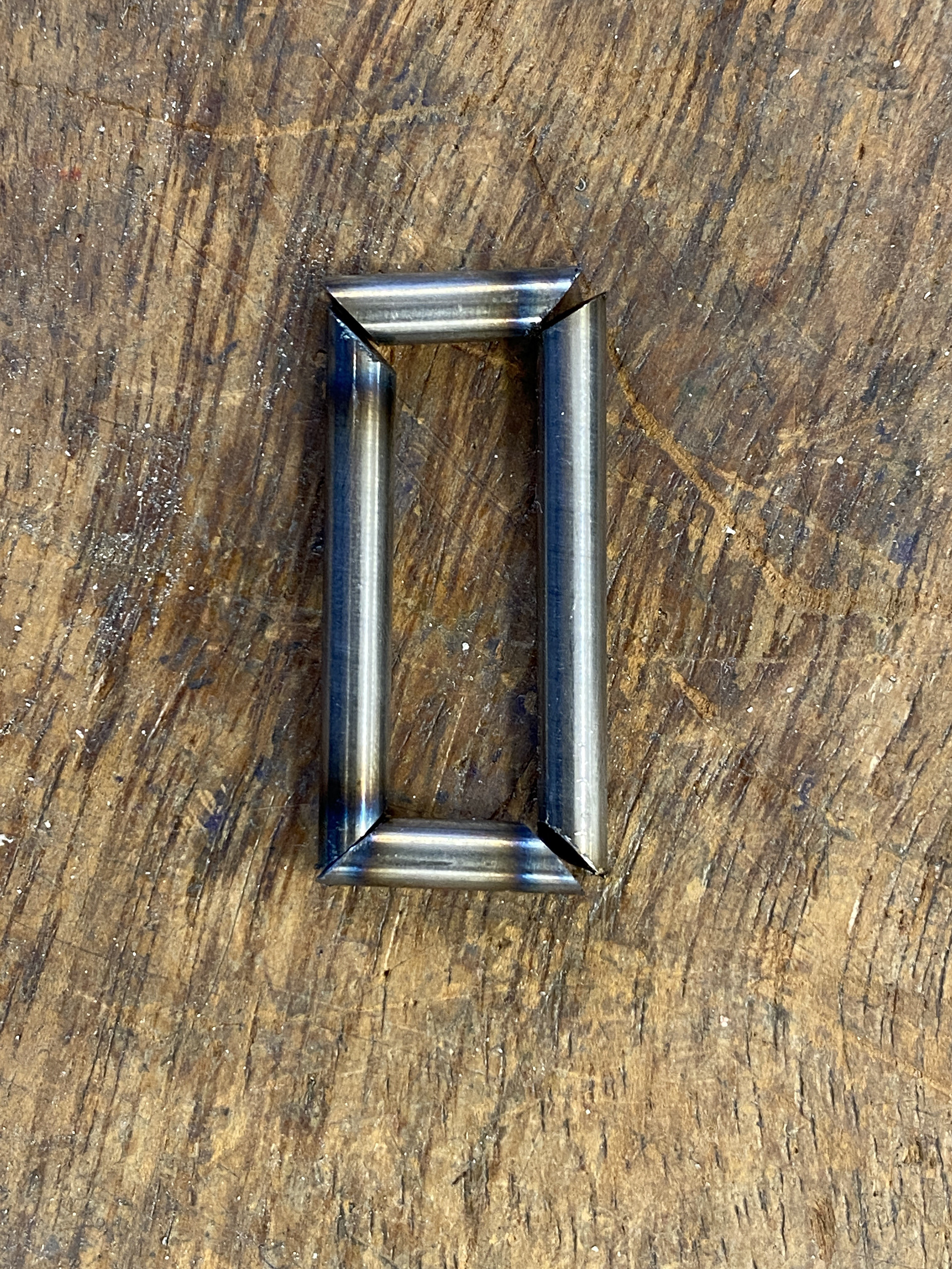
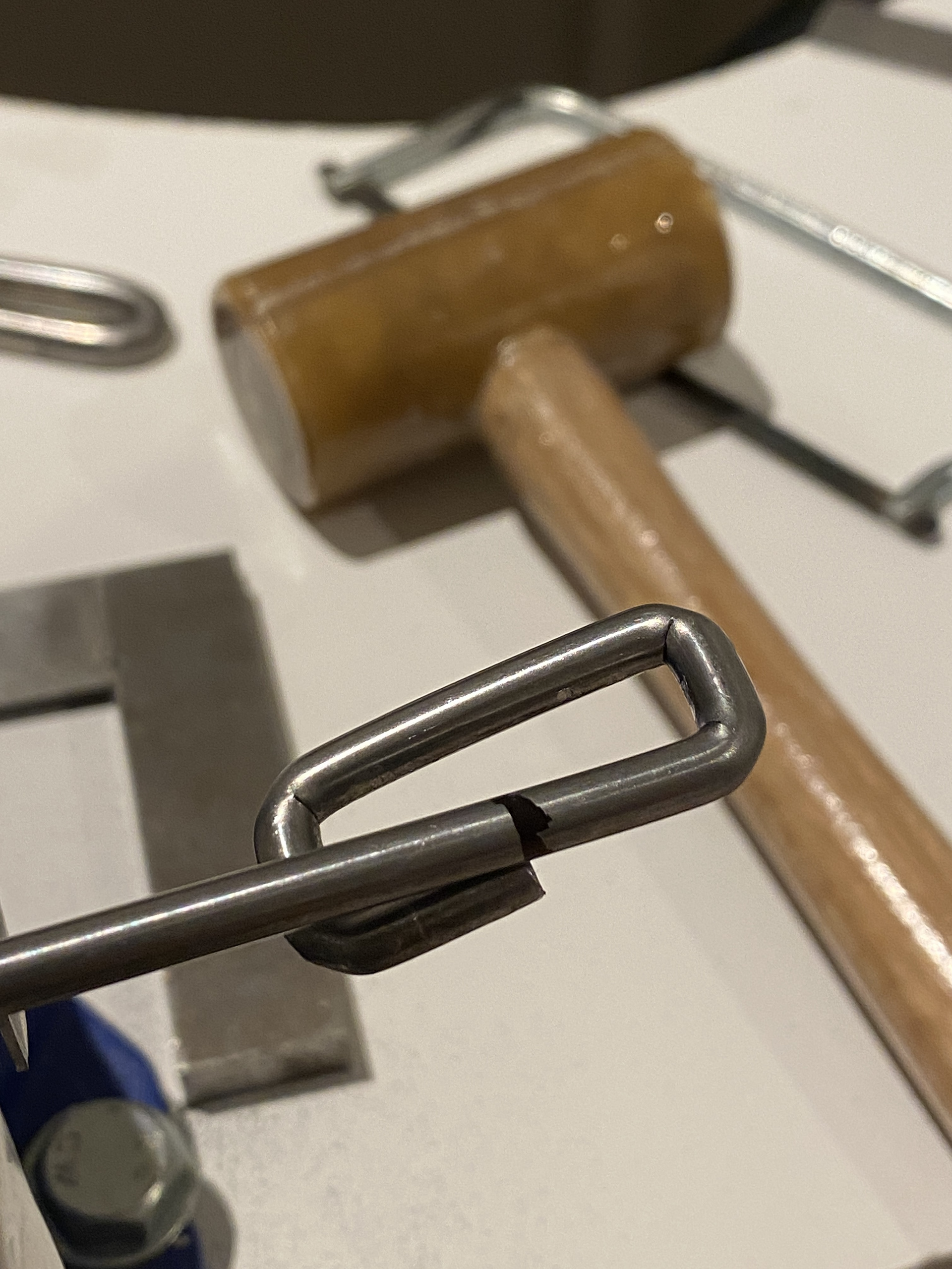
I also, made a refined a symmetrical hook that will be produced from 3mm steel rod. However, this felt too fragile and disproportional, meaning I will increase the material thickness in the future. Finaly, the space for the hook to latch onto is too tight.
I created a series of improving designs for the hook, focusing on increasing the material thickness and ease of connection. I kept the lover rectangles internal width consistent (30mm) so that the leather strap (25mm) would comfortably be able to loop around it. I found that increasing the material thickness to 5mm gave a nice balance between strength and the tactile feeling of hooking it onto the clasp, whilst not being overpowering.
I a narrower hook section but felt that this was too angular and didn't feel cohesive with the circular nature of the chain piece. Therefore, I tried a rounded V shape, which I felt hooked cleanly onto the clasp and felt visually more cohesive.

To solve the hooking problem, I went back to a previous design which had a larger area.

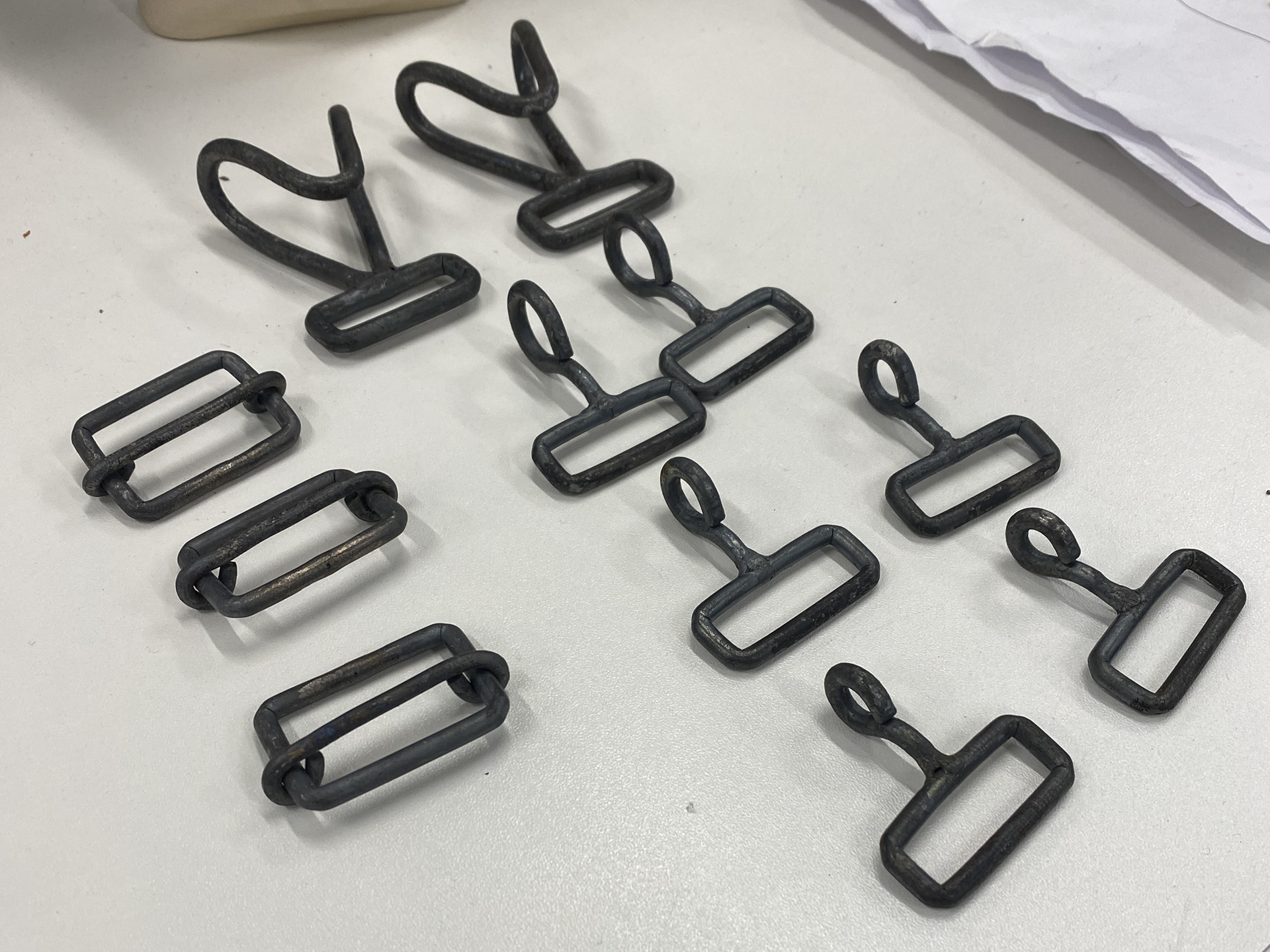
For the top section clasp I felt a simpler design as necessary, not to overcomplicate the back of the piece. I knew that there needed to be two permanent connections and one that could be unhooked. I went through the same developmental process of card to 3D printed and worked out the final design with two simple half links attached to a main one that could be hooked onto by the V shaped hook.
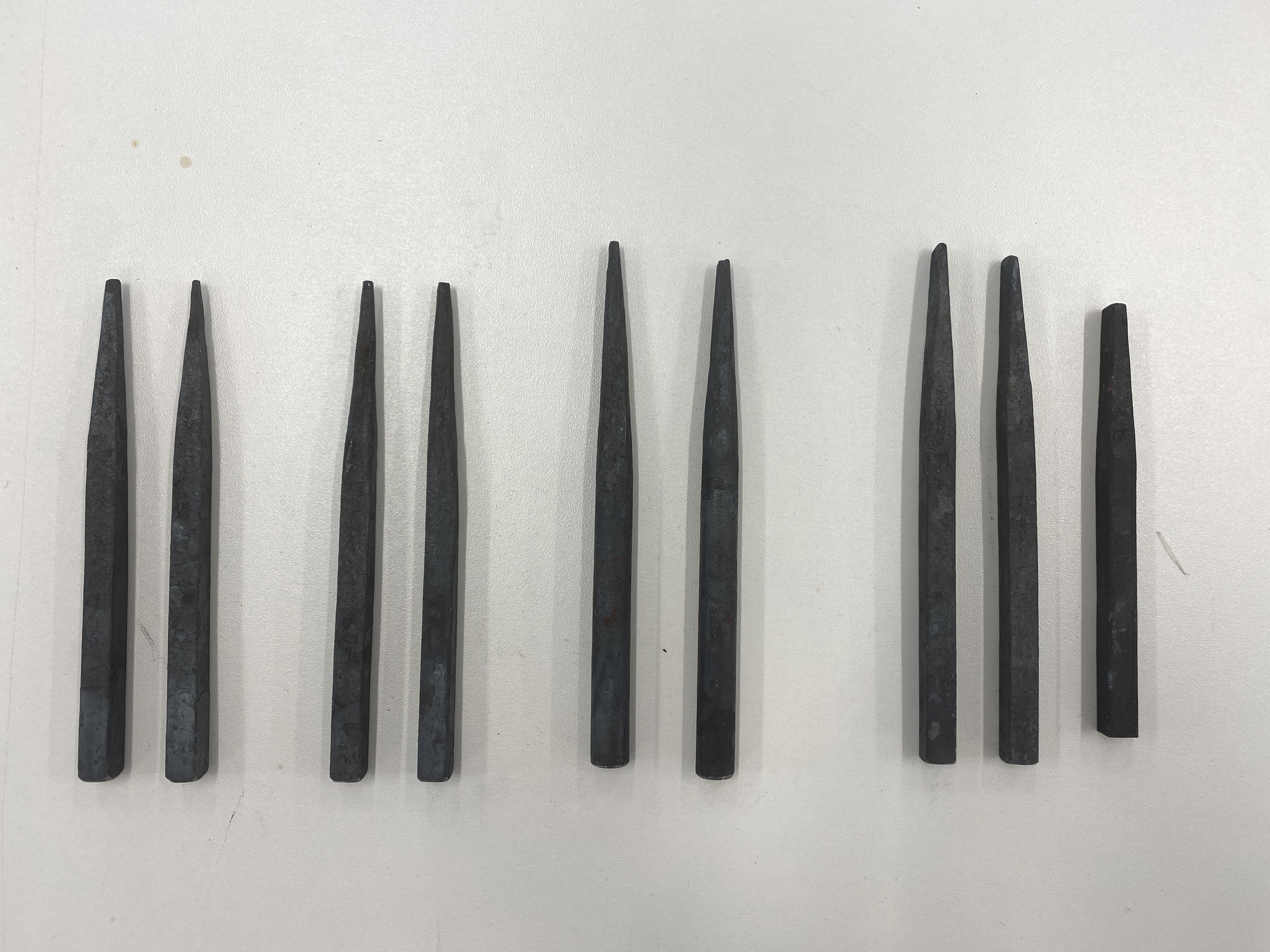
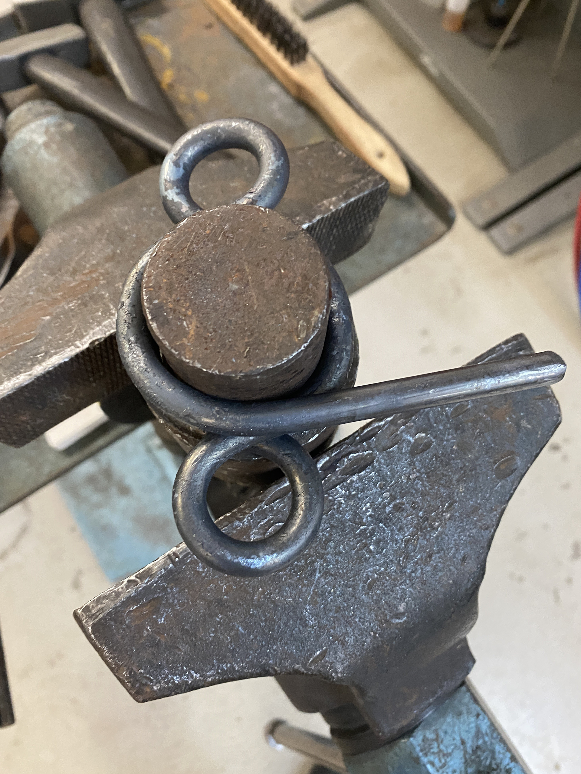
Creating jigs for the large hooks

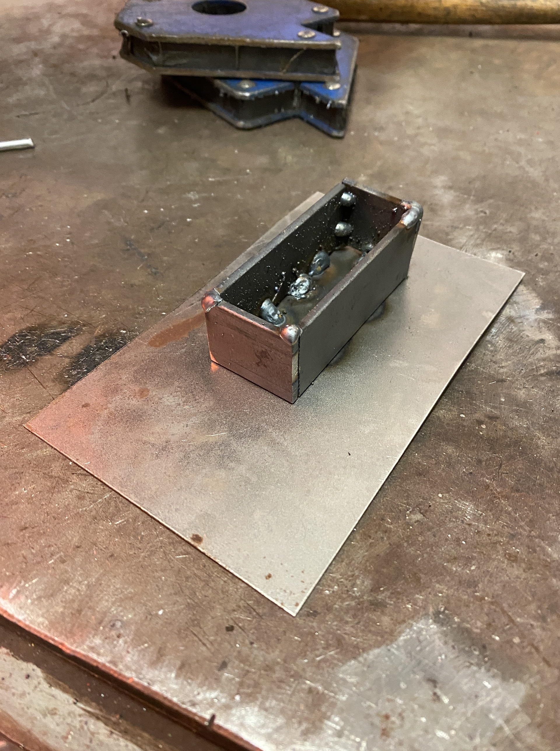
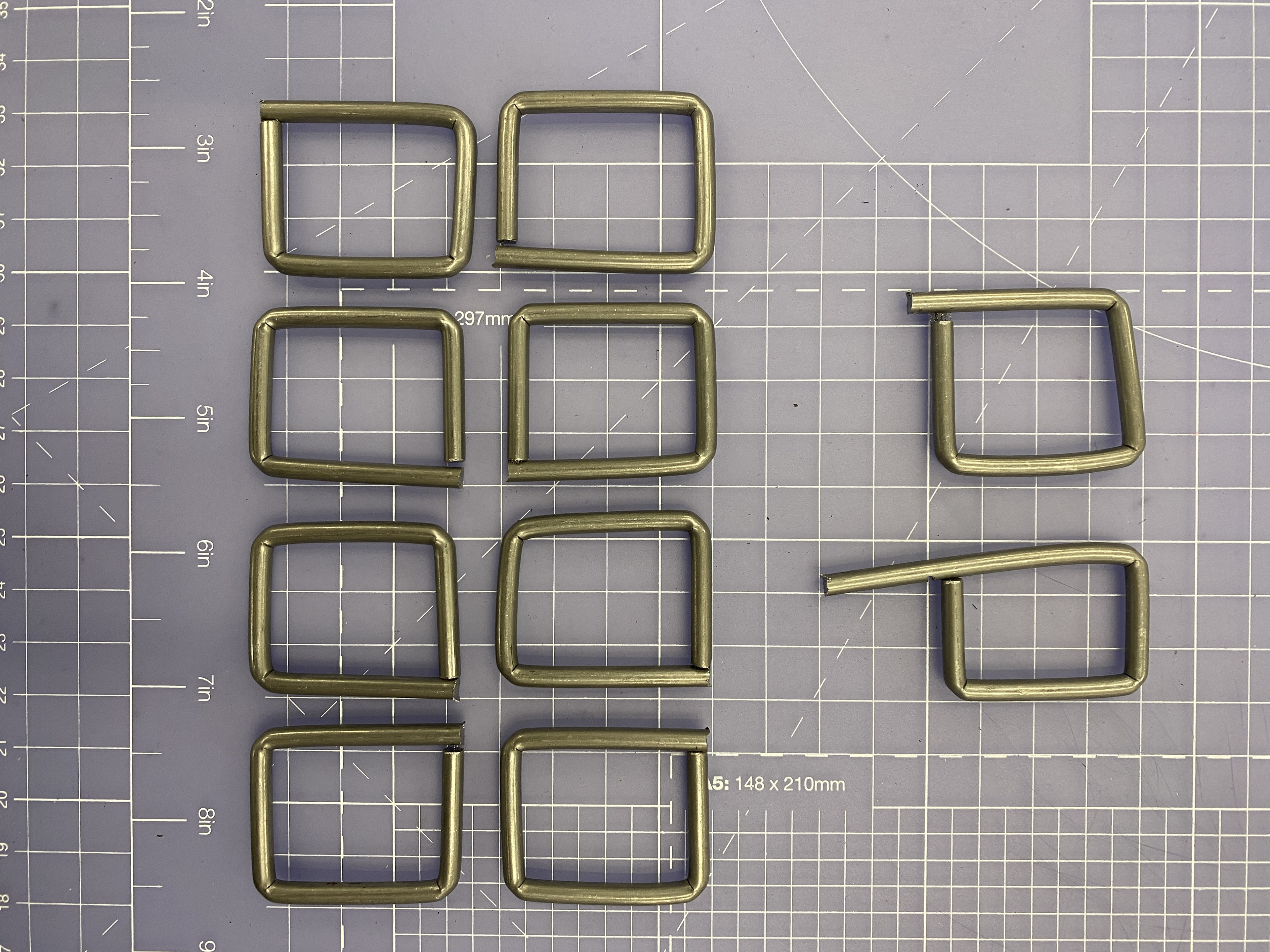
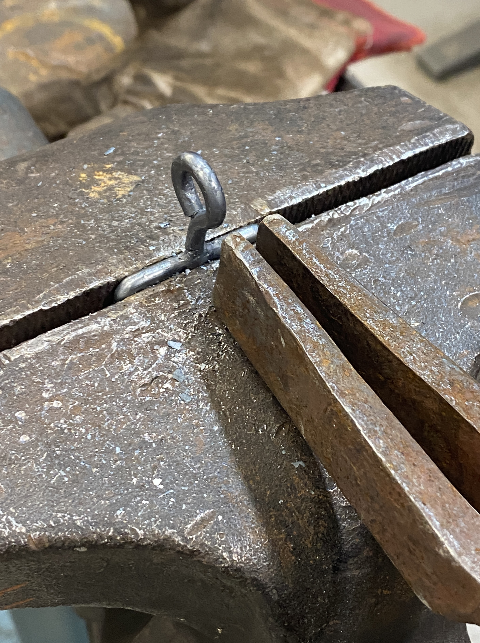
Before making the more complex V shaped hook I wanted to test making a jig for the simpler rectangular design. I cut down a large section of angle iron to make the internal 8x30mm for the strap and then welded a rectangle from flat bar to a base plate. This jig was designed so that a rod could be stretched and hammered around it. The flat piece would then be bent around a rod to create the hook.
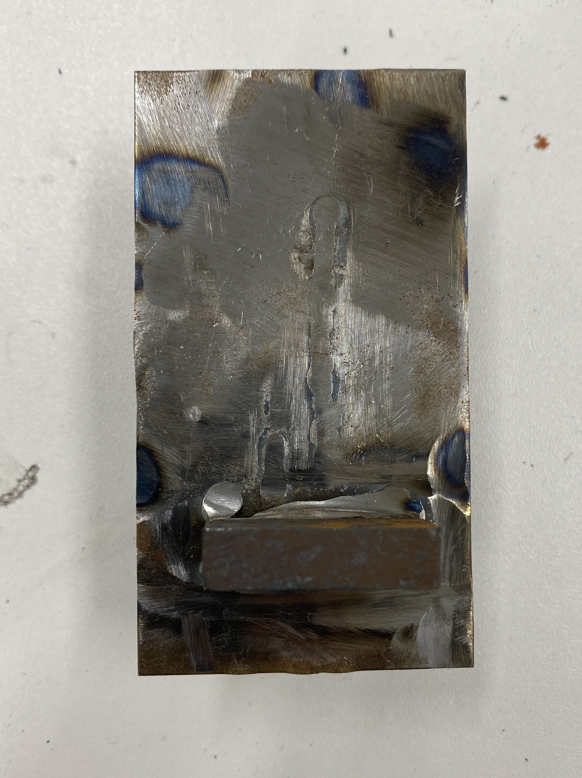

In practice the first jigs were unsuccessful as the was no way to easily hold the rod against the walls so it would slip and not give a clean bend. Additionally, the welds were very weak as I had to grind away most of it so that the rod could sit flush against the jig.
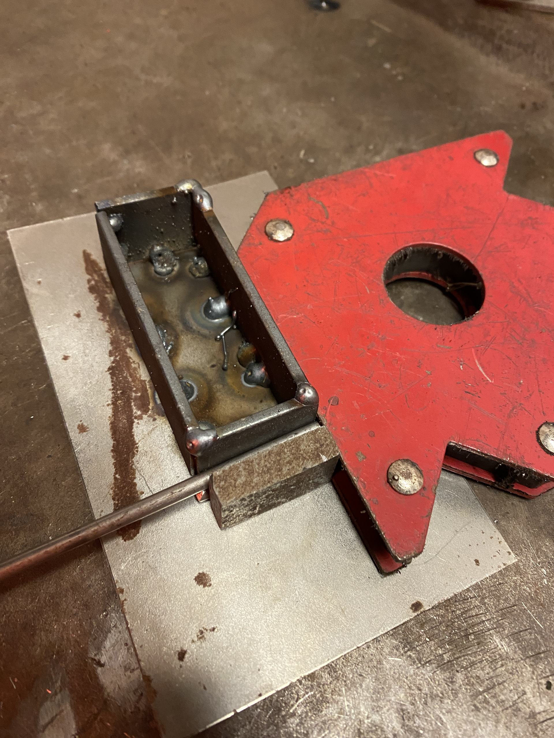
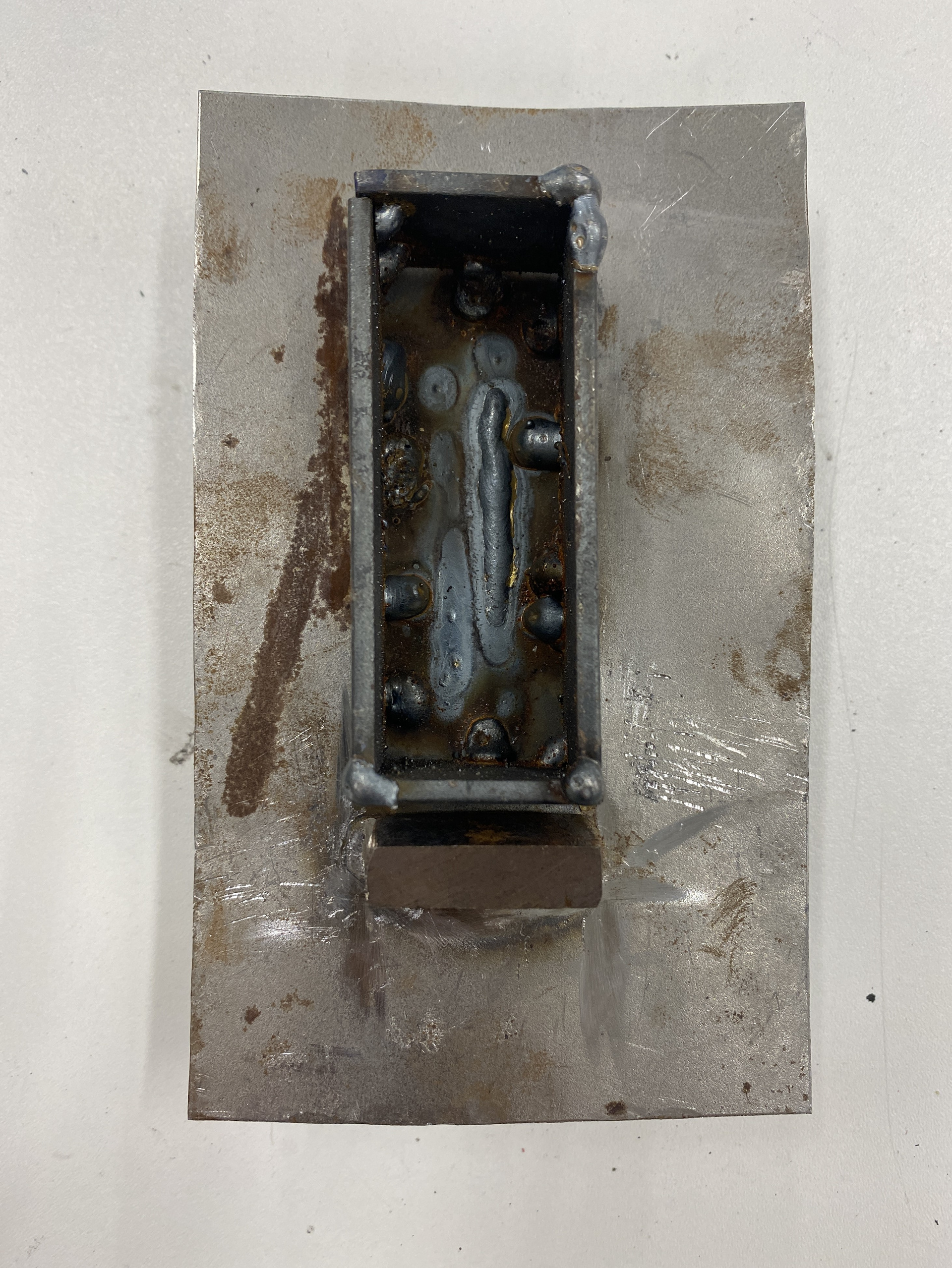
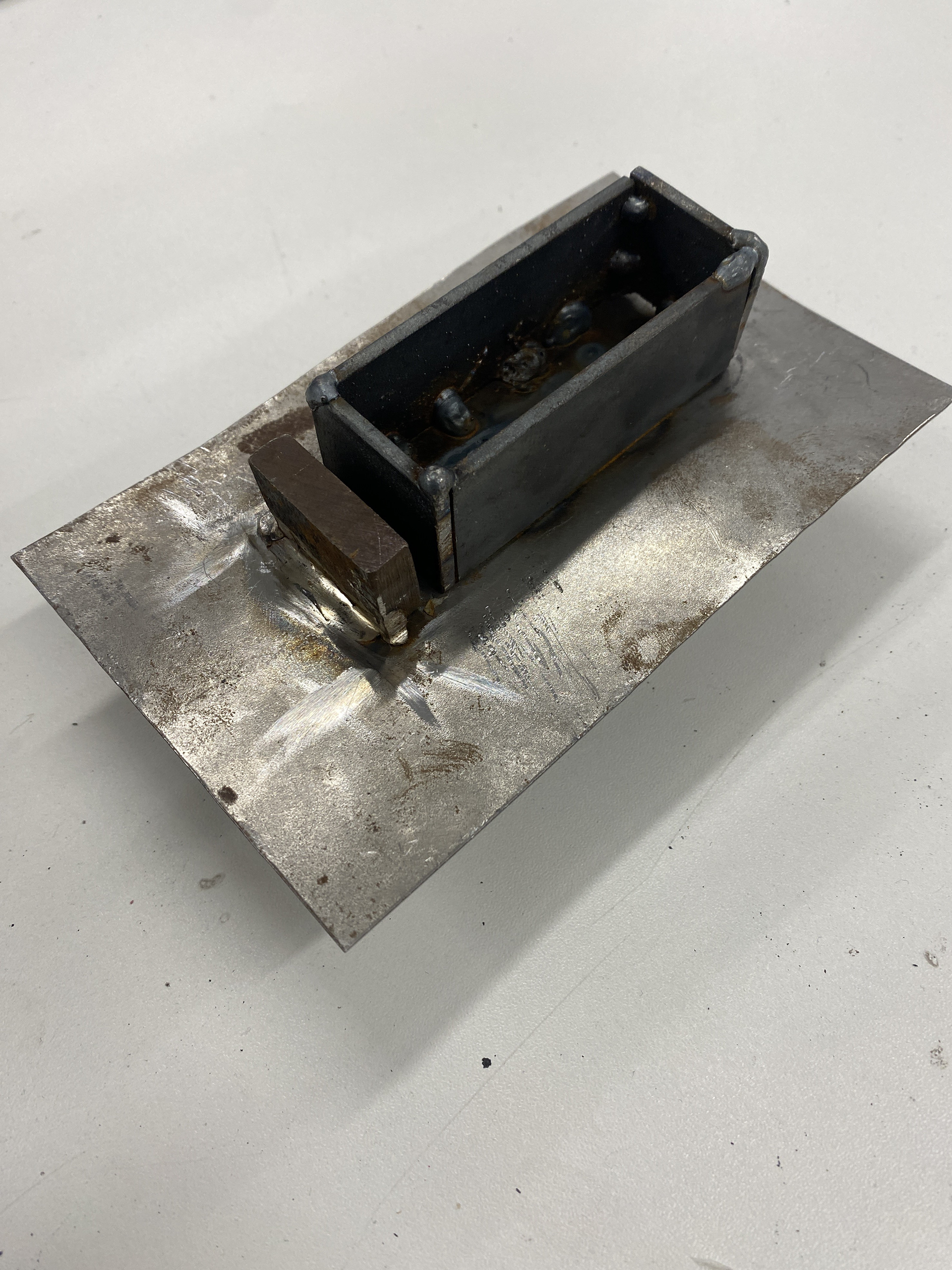
As my previous jig had failed and I wanted to make the V shaped hook I attempted to make a series of jigs for it instead. I broke down the piece into individual bends and jigs in fusion to give me a template and cut list. I transferred this onto sheet steel and cut flat bar for the walls of the jig. This initially worked for the first couple of bends however, they were resulting in a much more rounded bend than a square right angle.

I ended up needing to add an additional jig as I had thought that it would be easier to do multiple bends on one jig, but this lacked the grip and resulted in the piece moving about too much. Finaly, these jigs didn't work. There were many issues with them however the main one was the quality of my welds. As I could only lay weld on one side of the walls and often this was in tight spaces that the torch didn't properly fit into, the welds all broke.
Another issue was working with the steel hot, I had to rely on using hammers and tongs to force the rod against the jig, this was most likely one of the reasons the welds kept breaking.
Testing bending the hooks by hand
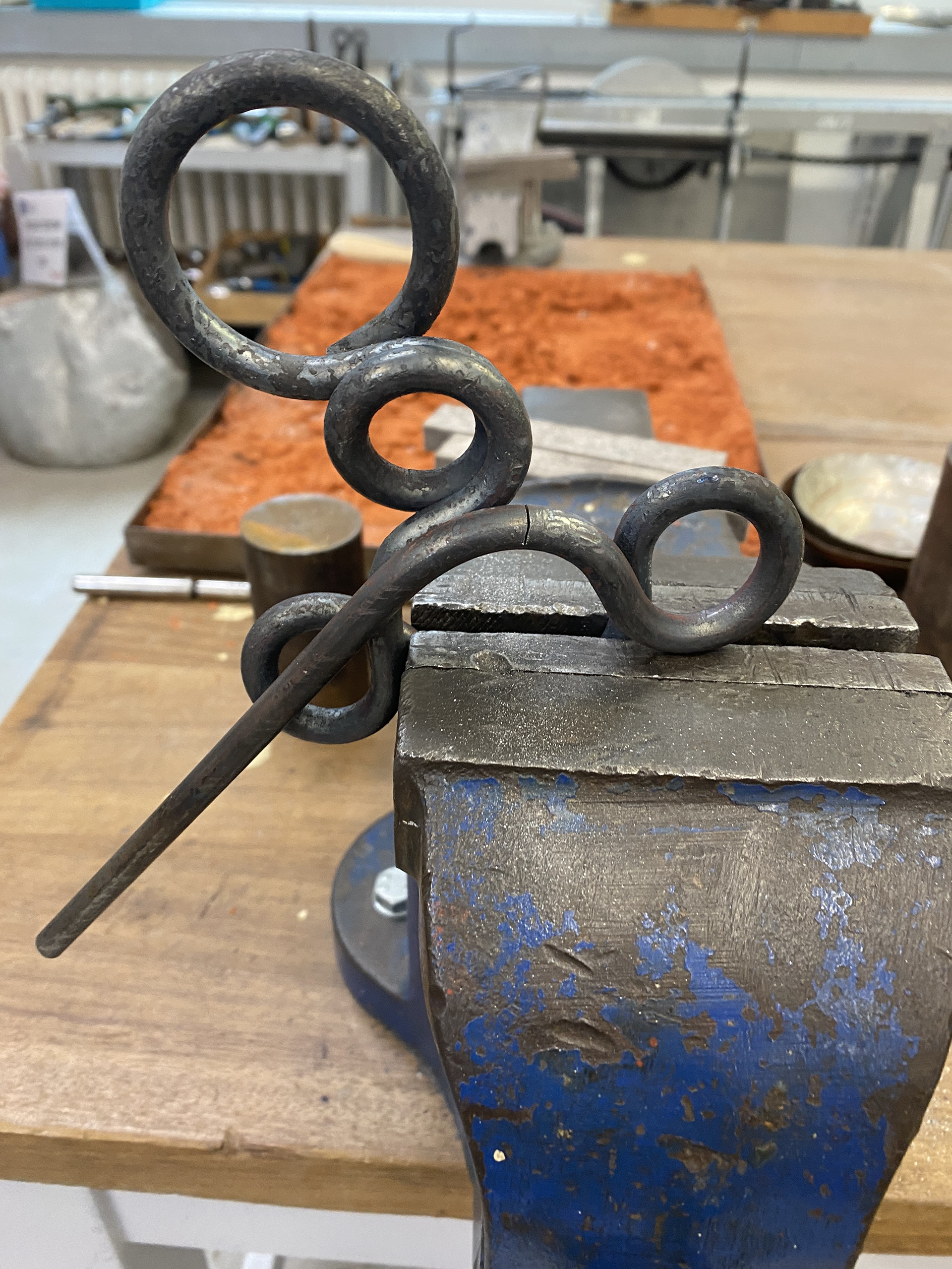
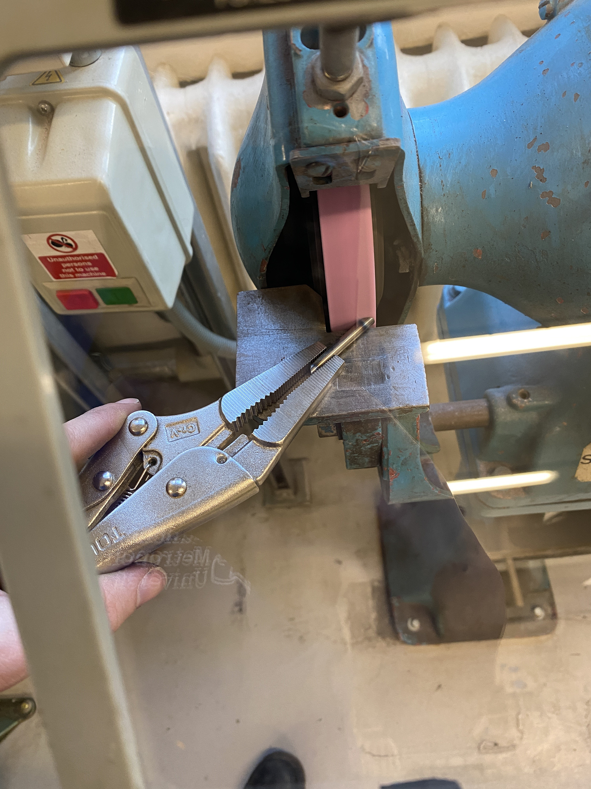
As the jigs failed, I resorted to trying to individually hand bend the rod cold.
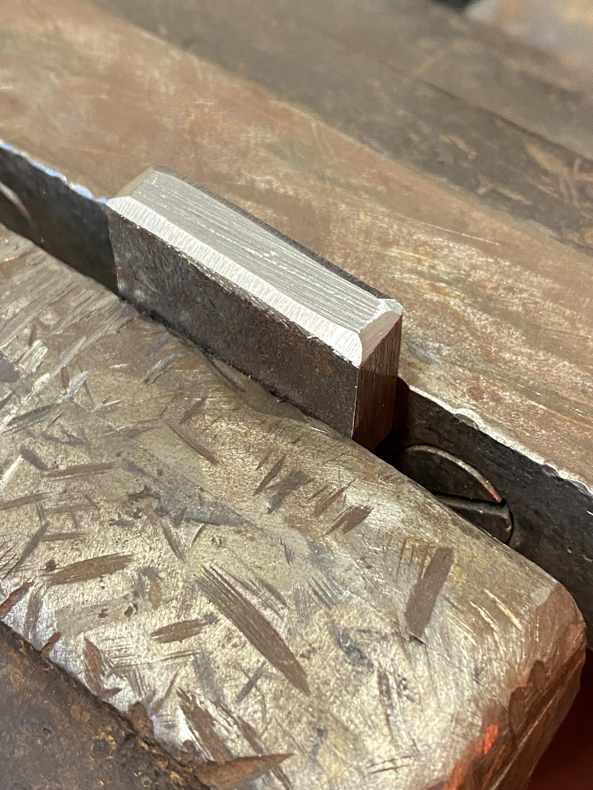
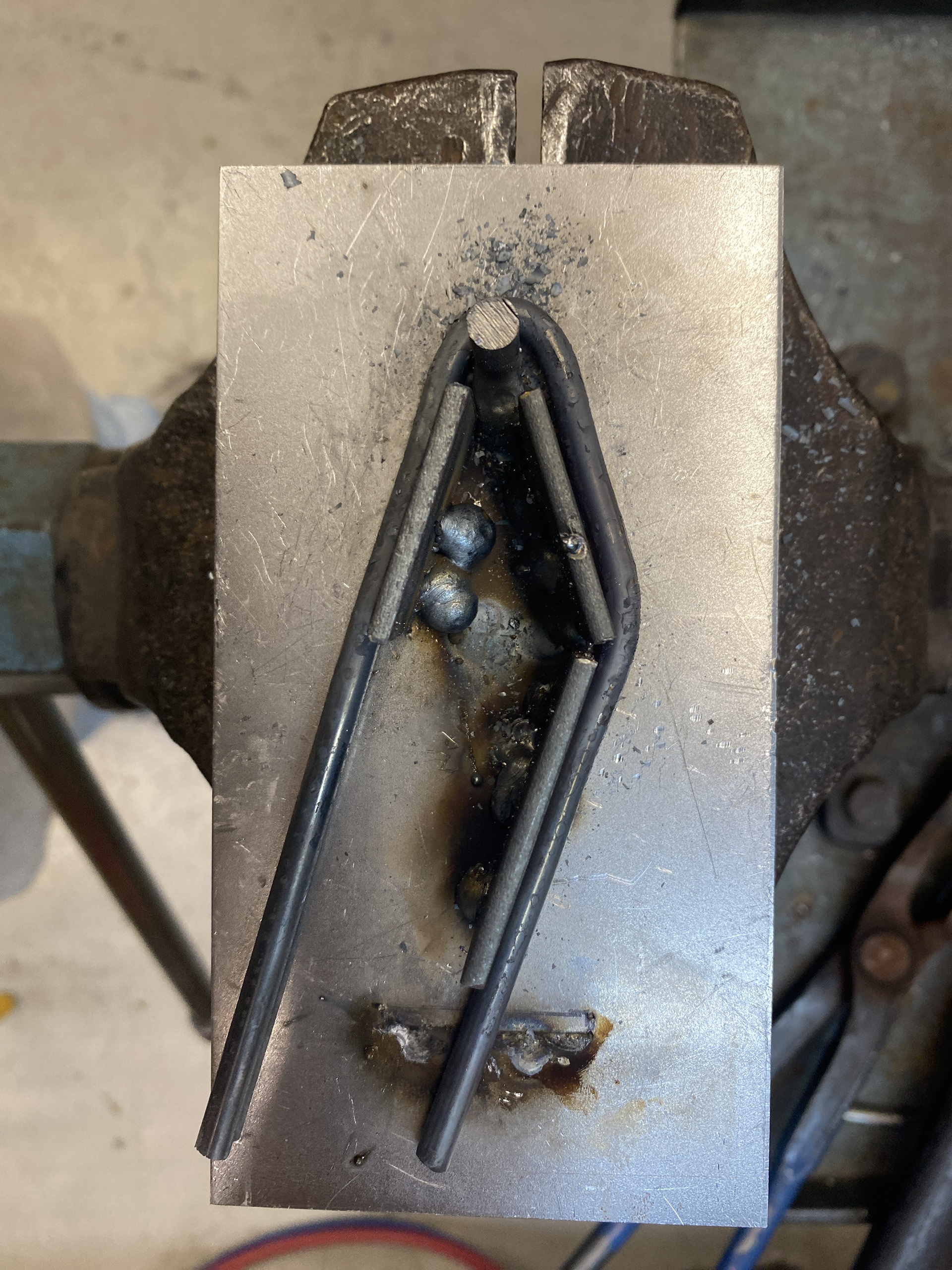
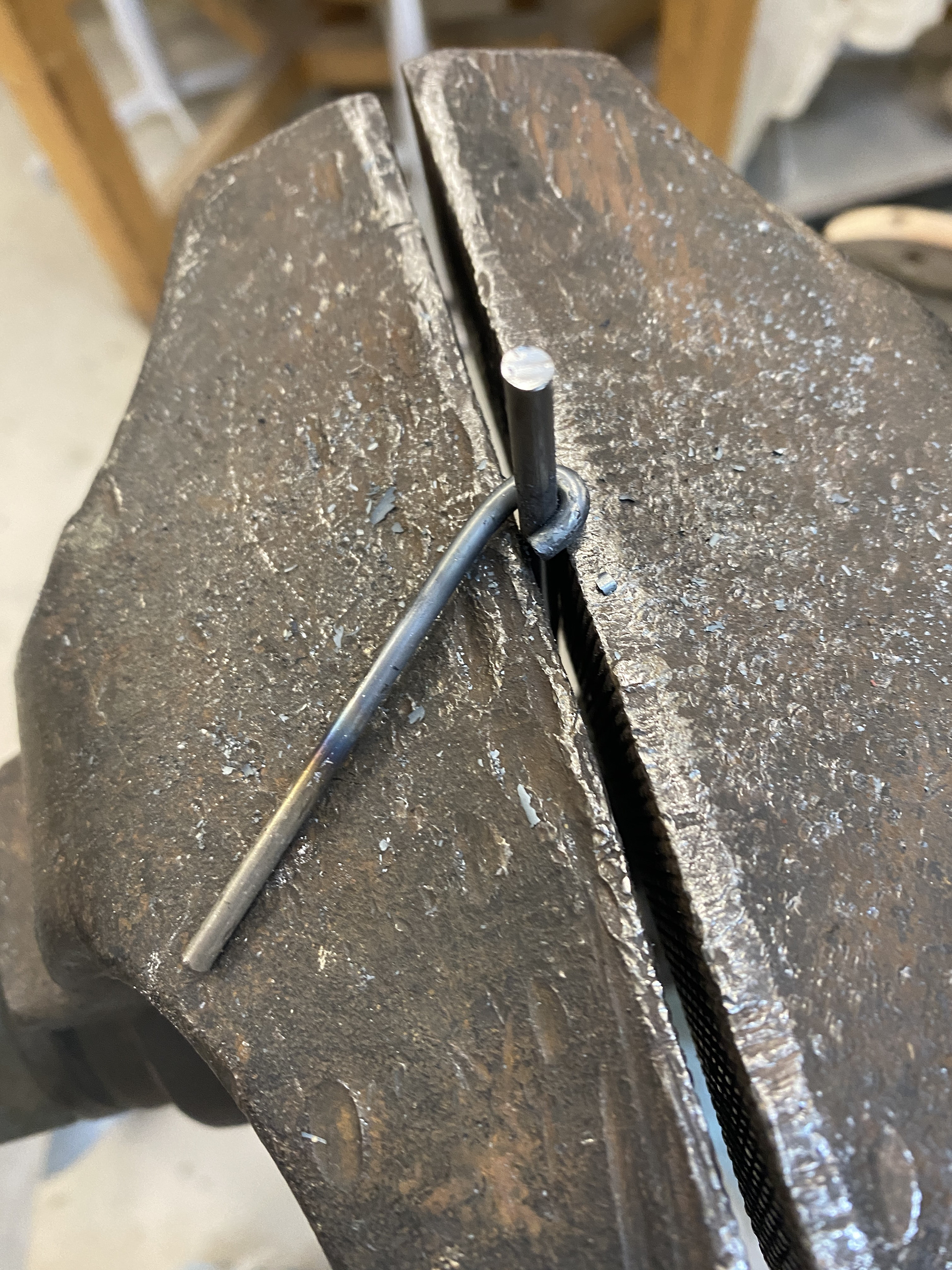
I found that the 5mm rod could be bent by hand in between a specialised tuning fork however, when I did so the bends were very rounded and created almost an overall rather than a rectangle. Therefore, I tested cutting in 45-degree slits at the corner concentrating the bending force, resulting in a much cleaner right angle. Through numerous tests I found that 10 stokes of the square file cut a deep enough grove to bend the corner to 90 degrees whilst not splitting or cracking the steel.
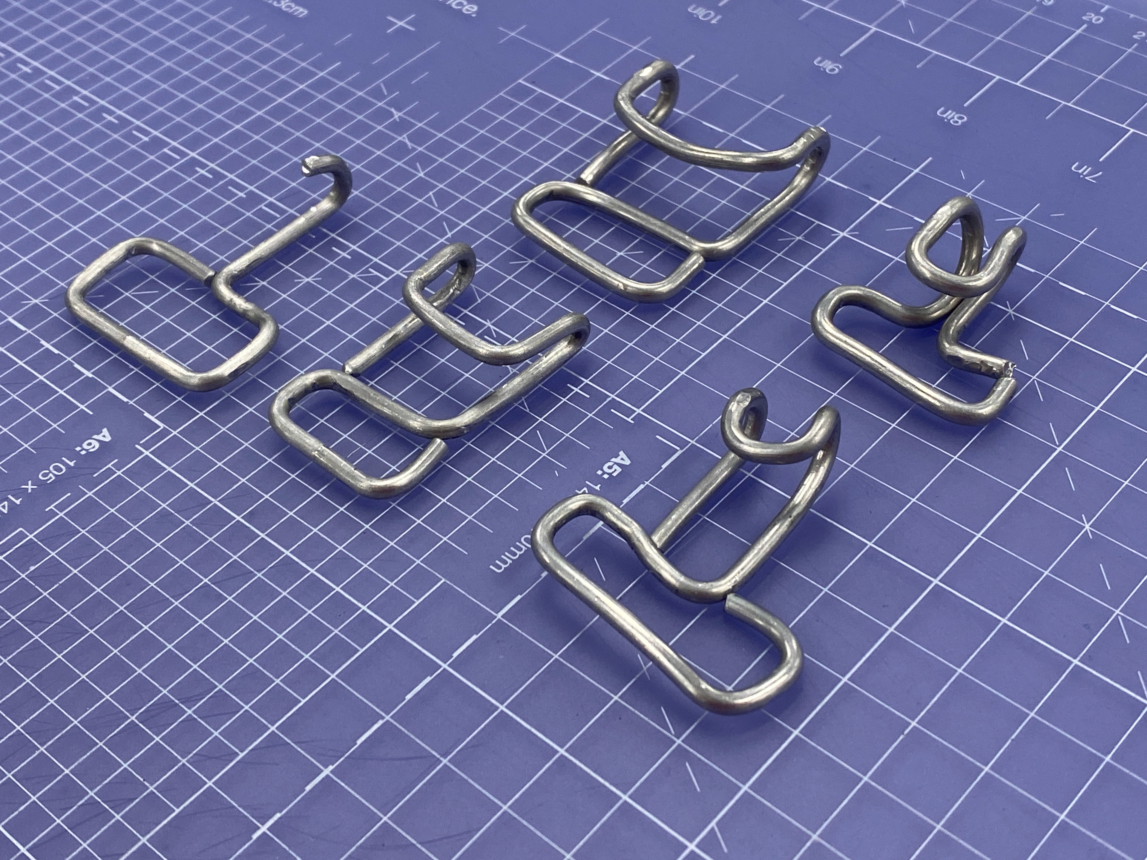
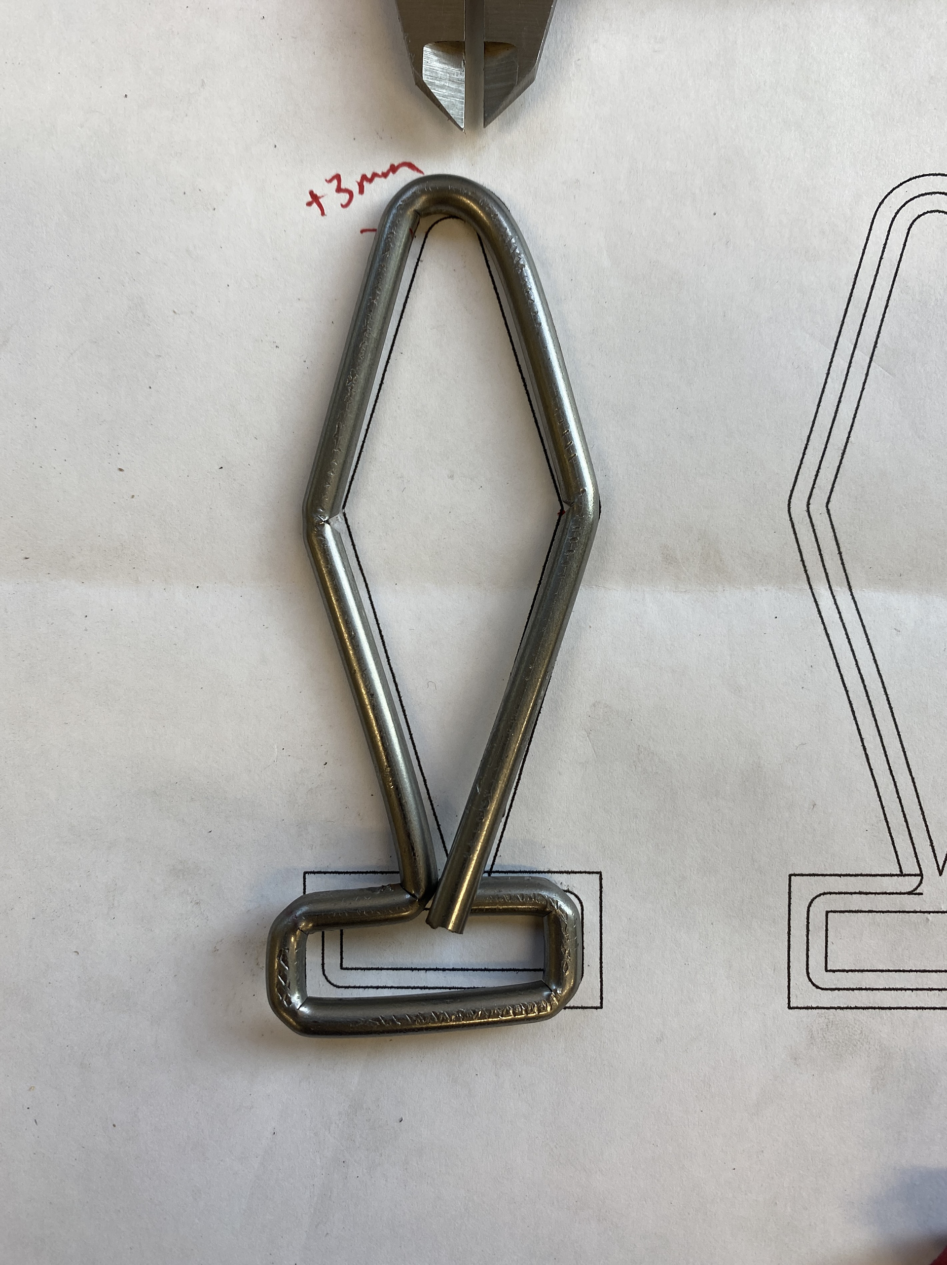
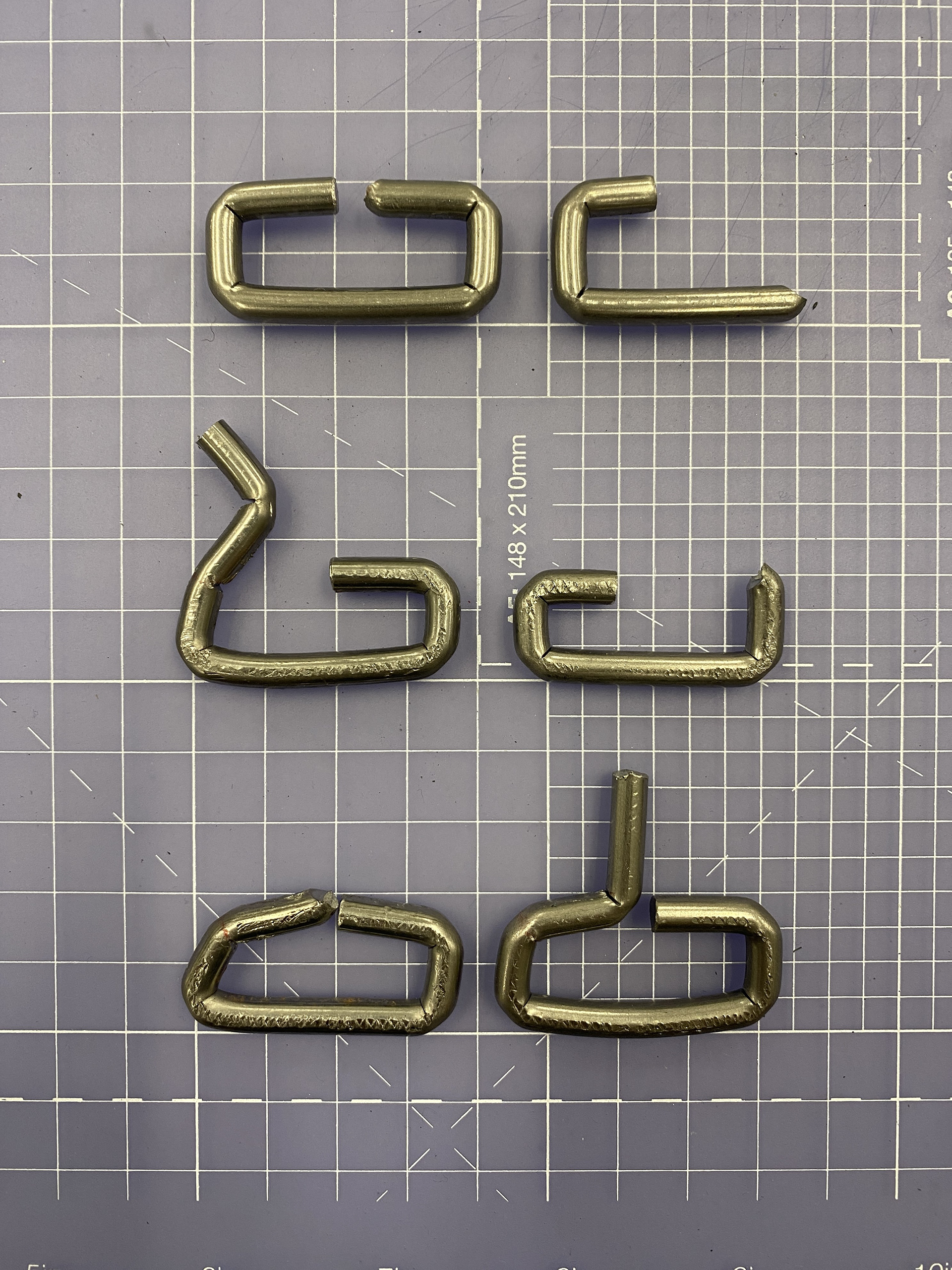
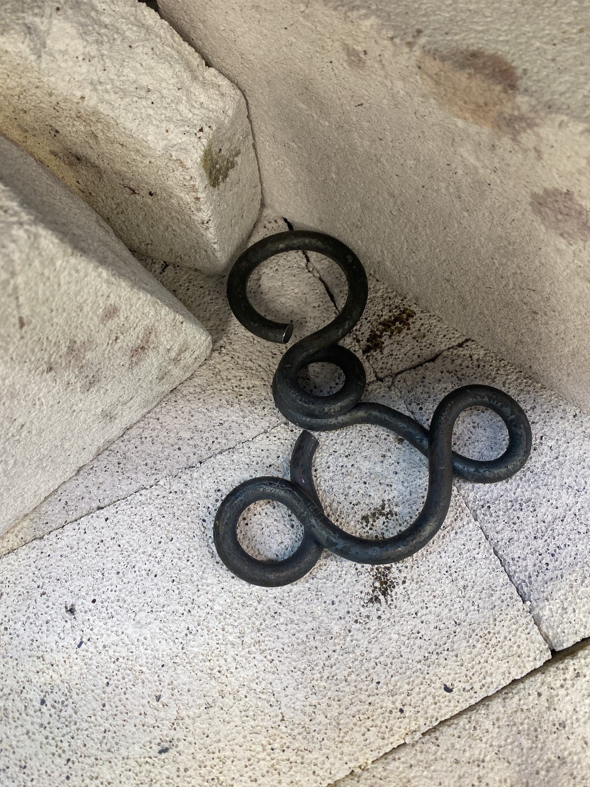
The next problem was the obtuse angle needed to make the diamond shape that would form the hook. I found that increasing the file strokes to 14 enabled this. My method was to bend this first then return to the previous 90-degree bend in the sequence to complete the rectangle. This was necessary as the steel rod would run into itself when trying to bend all the right angles first. However, this sequence meant that I would need to tap this last right angle into place rather than pushing on the rod, as this would undo the obtuse angle. This resulted in a distorted rectangle, as the lower left bend would often move rather than the top left (as seen in the images above).
I then tried as different bending sequence, starting in the middle of the rod and forming from the top of the hook first. This order meant that I needed to bend two of the obtuse angles which both snapped when I attempted it.
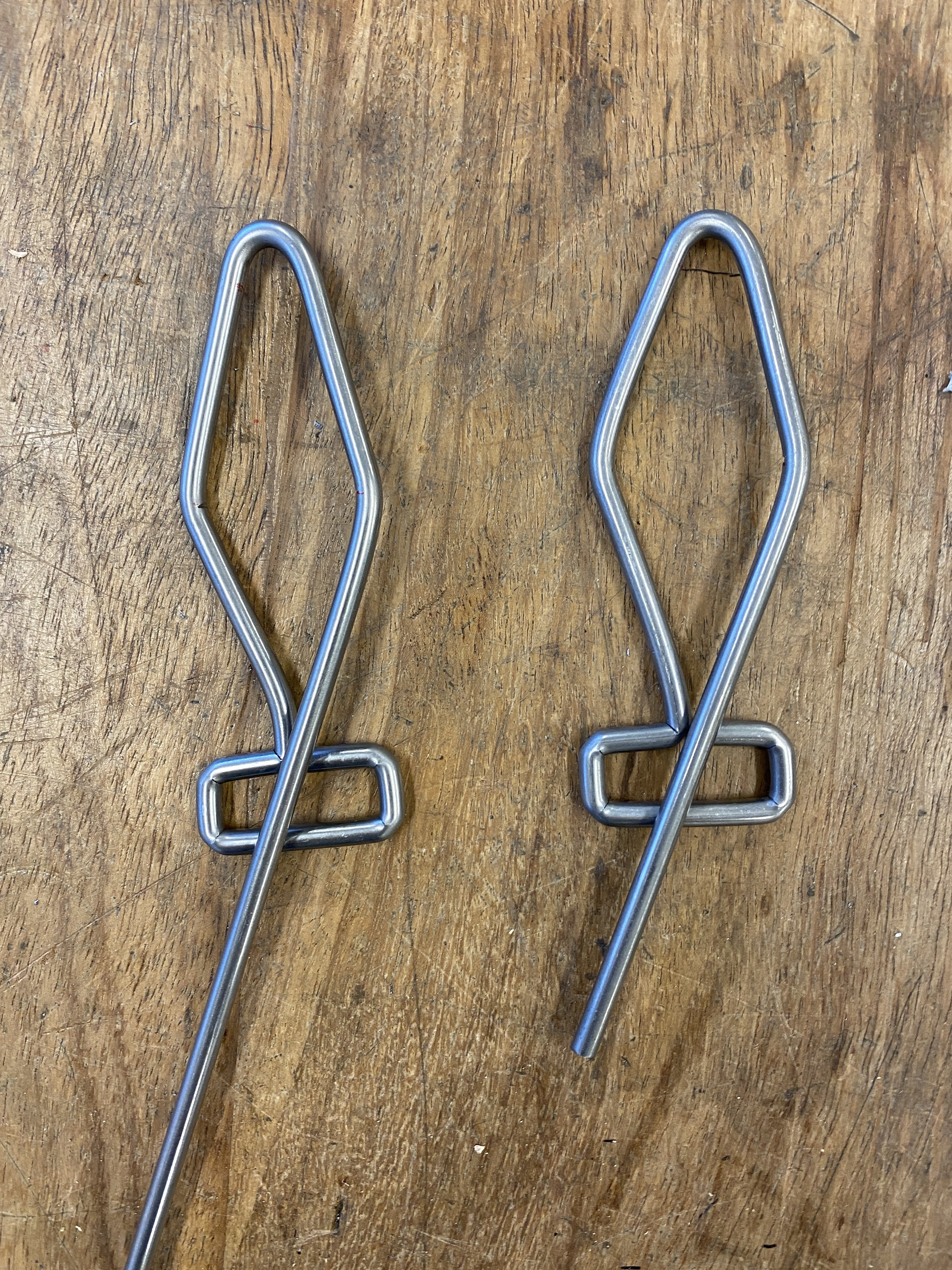

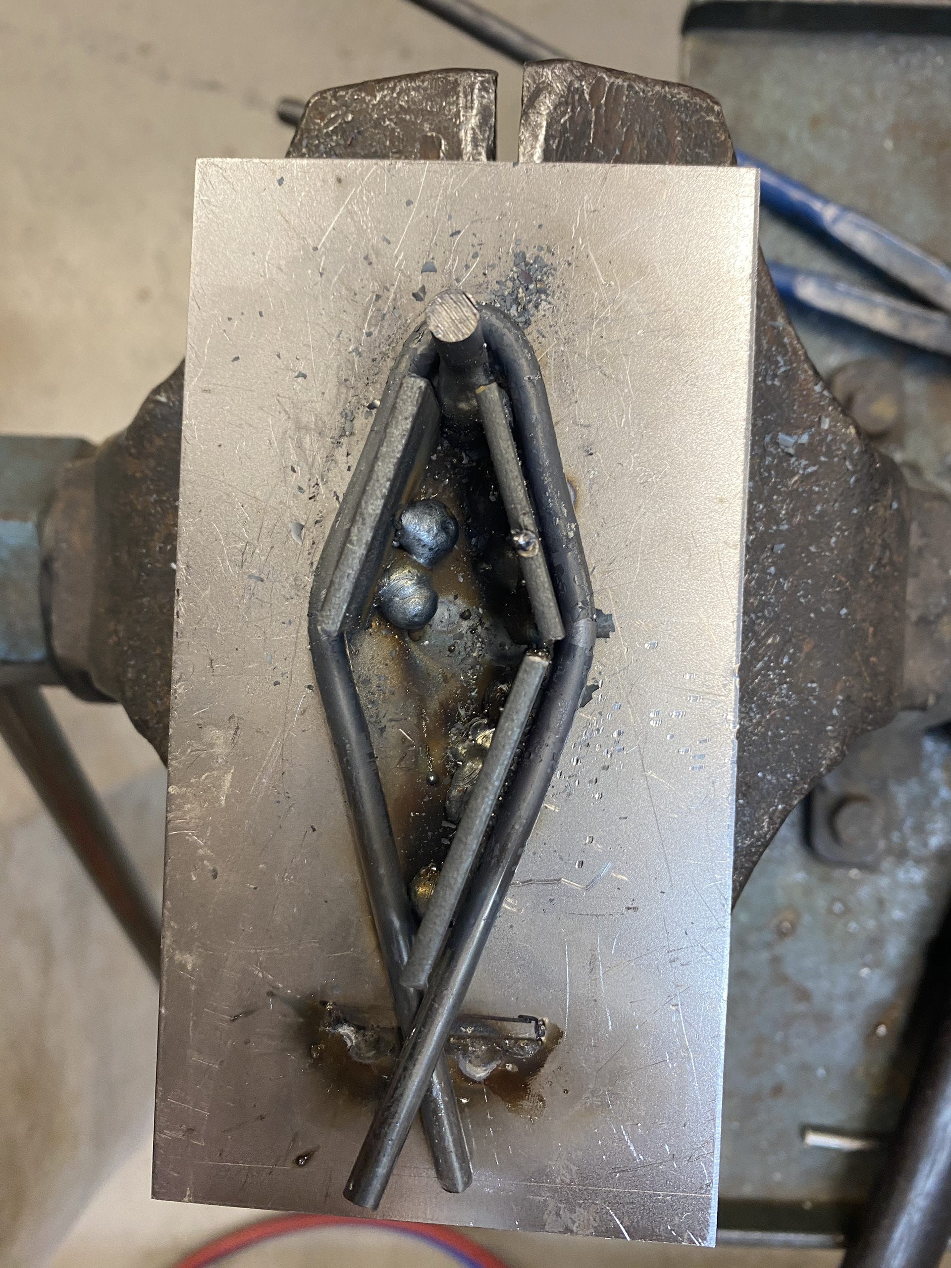
I tested a different bending sequence where I completed the rectangle by overlapping the rod in the middle section before bending the obtuse angle. This worked to some degree, the piece was close to the design drawing however, there was some areas where the angles and lengths were off.
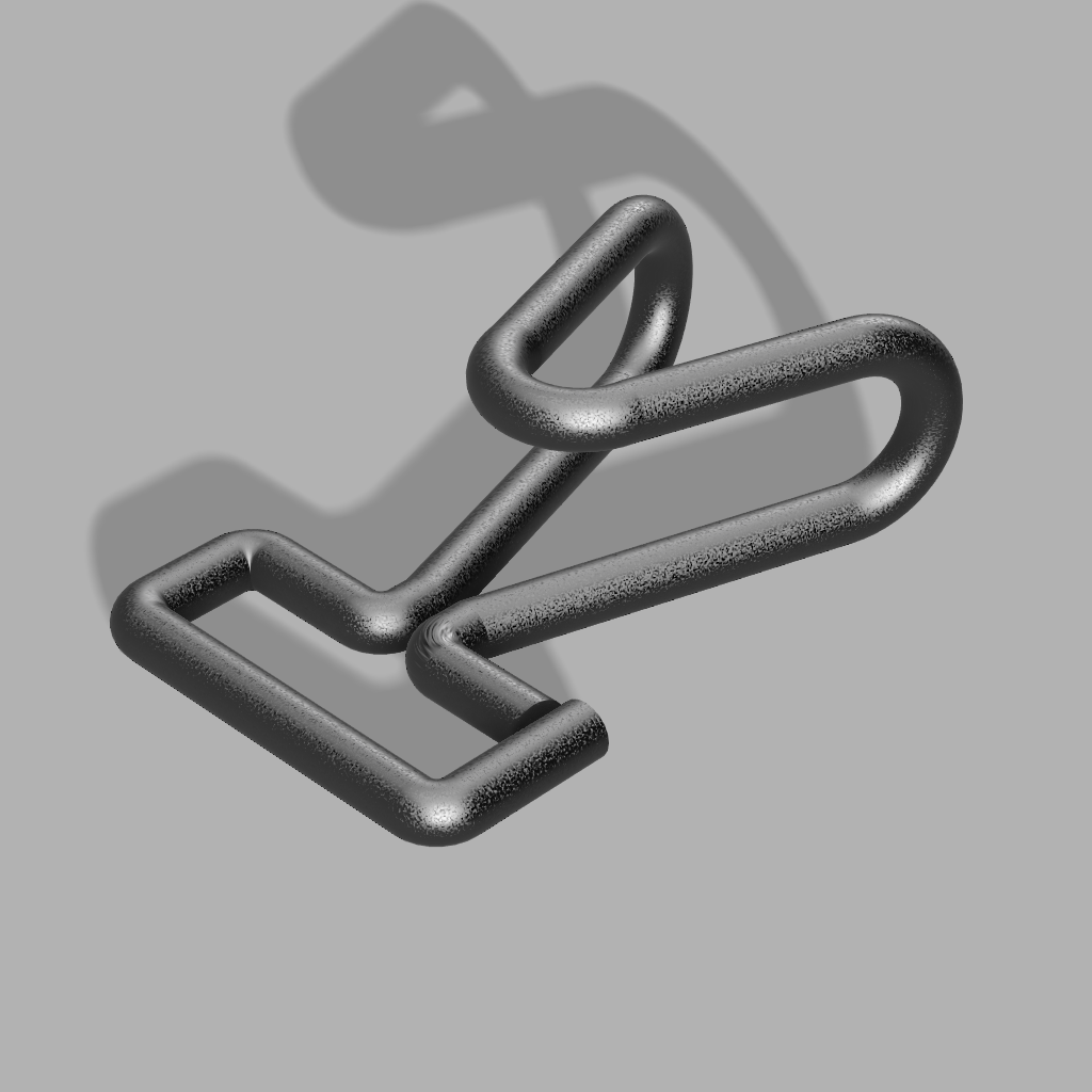
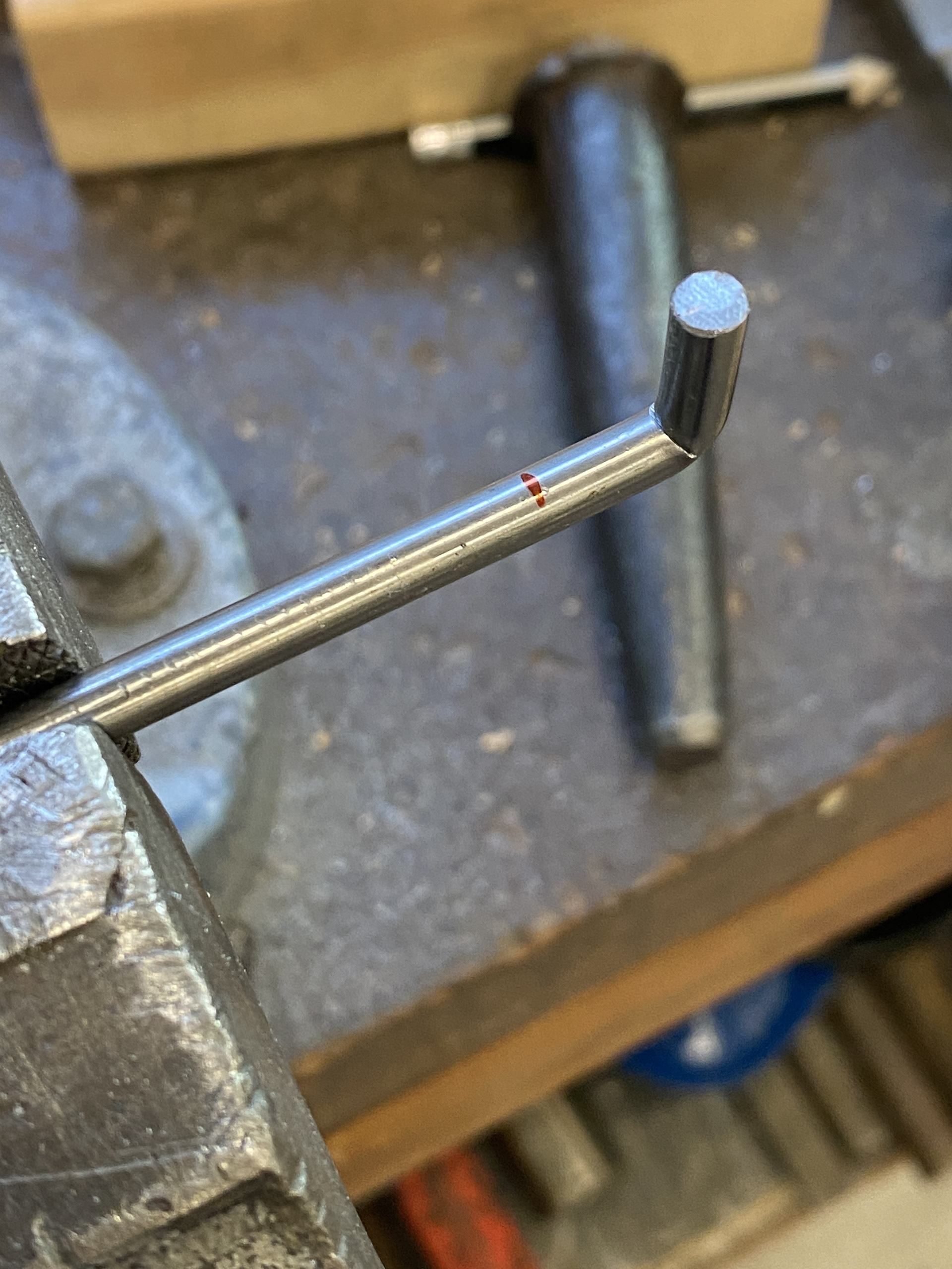
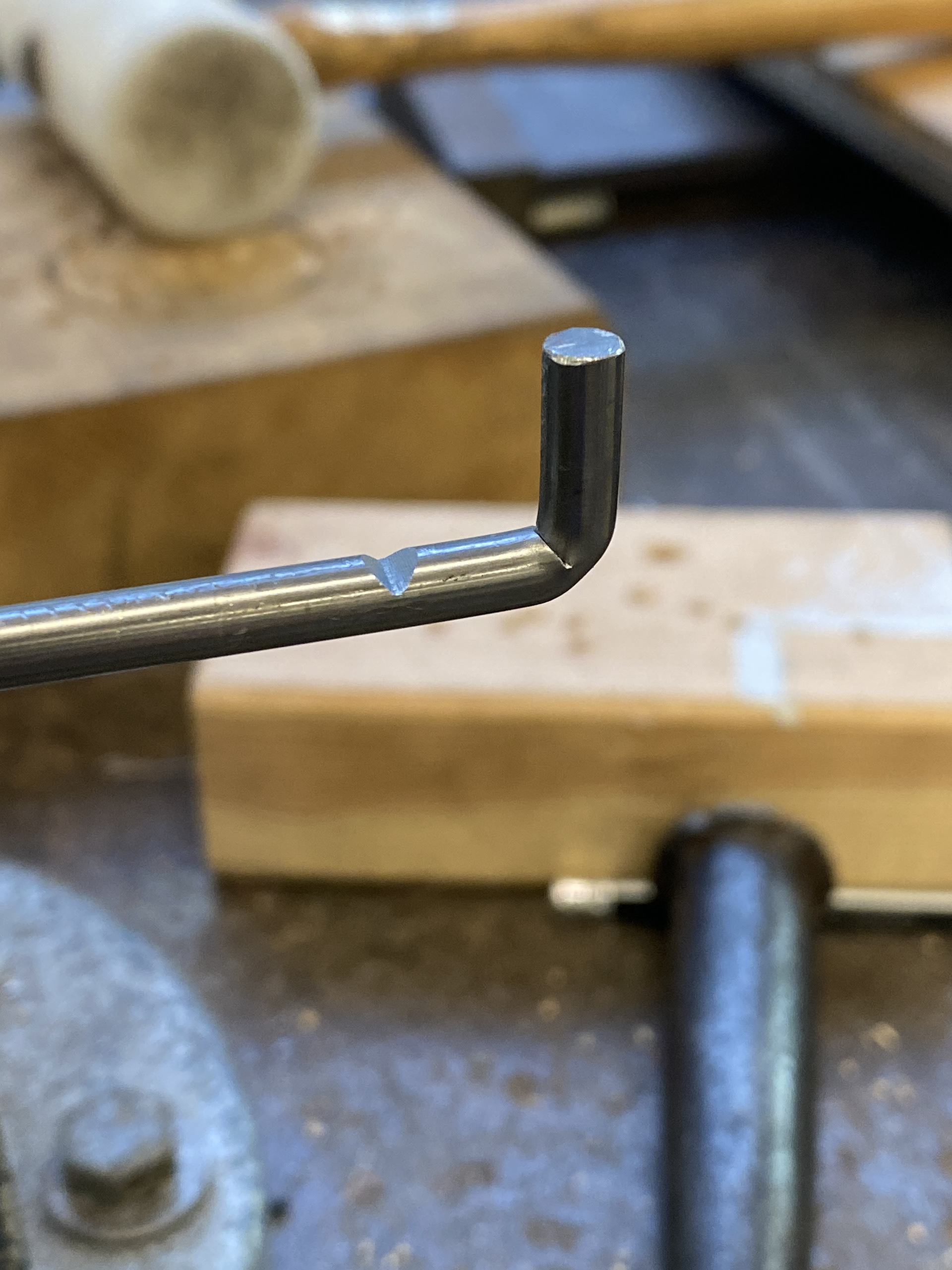
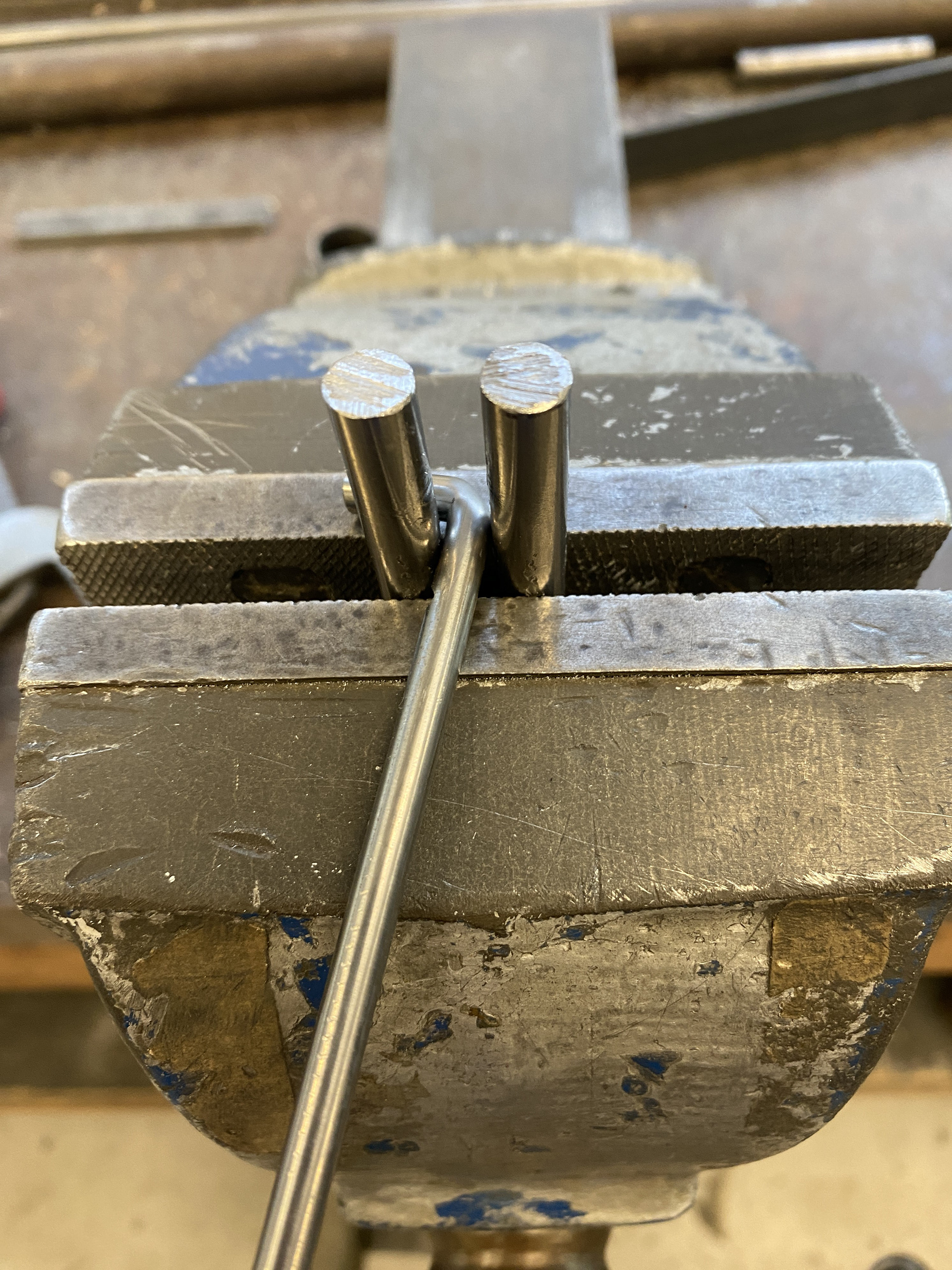
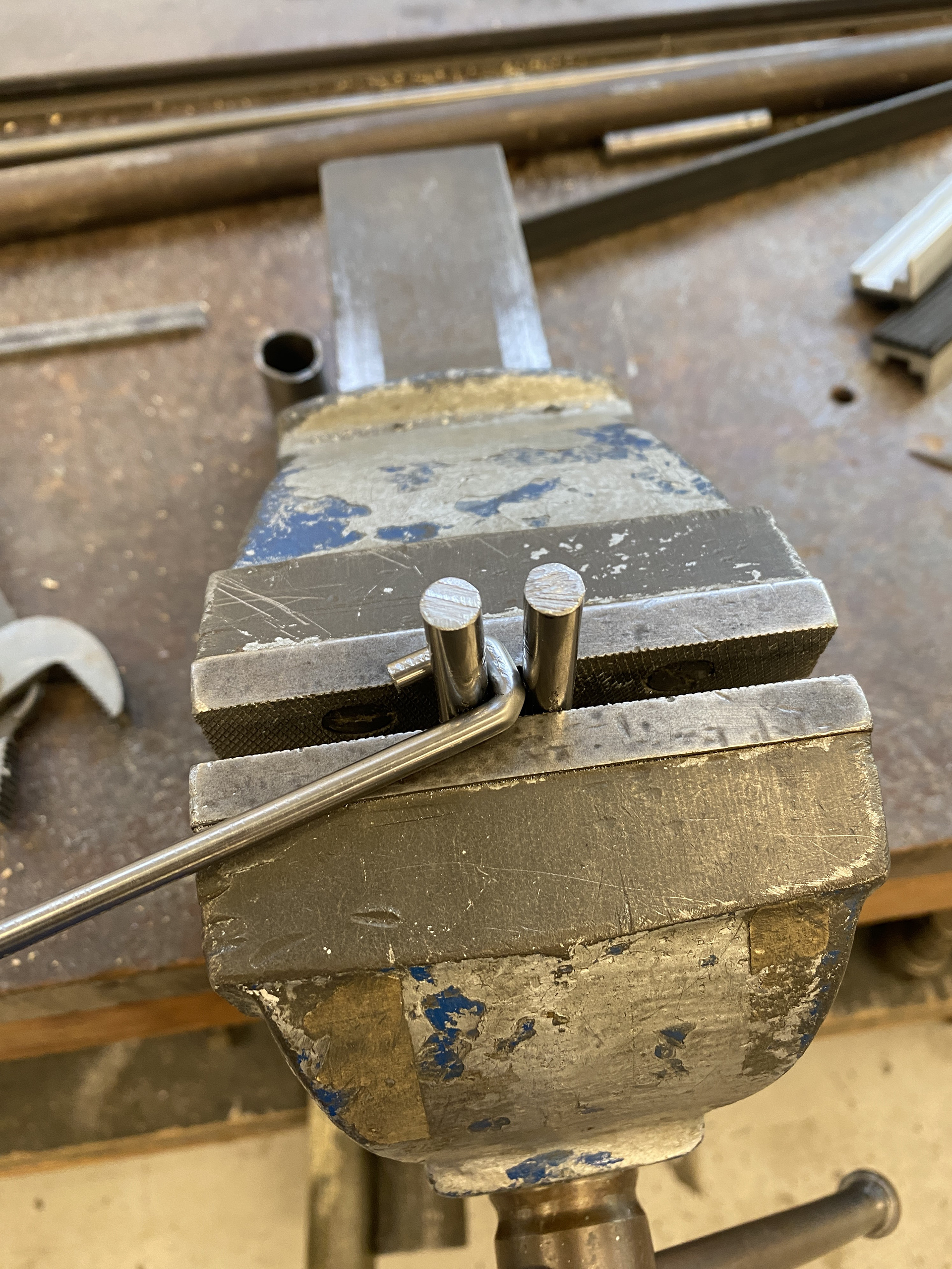
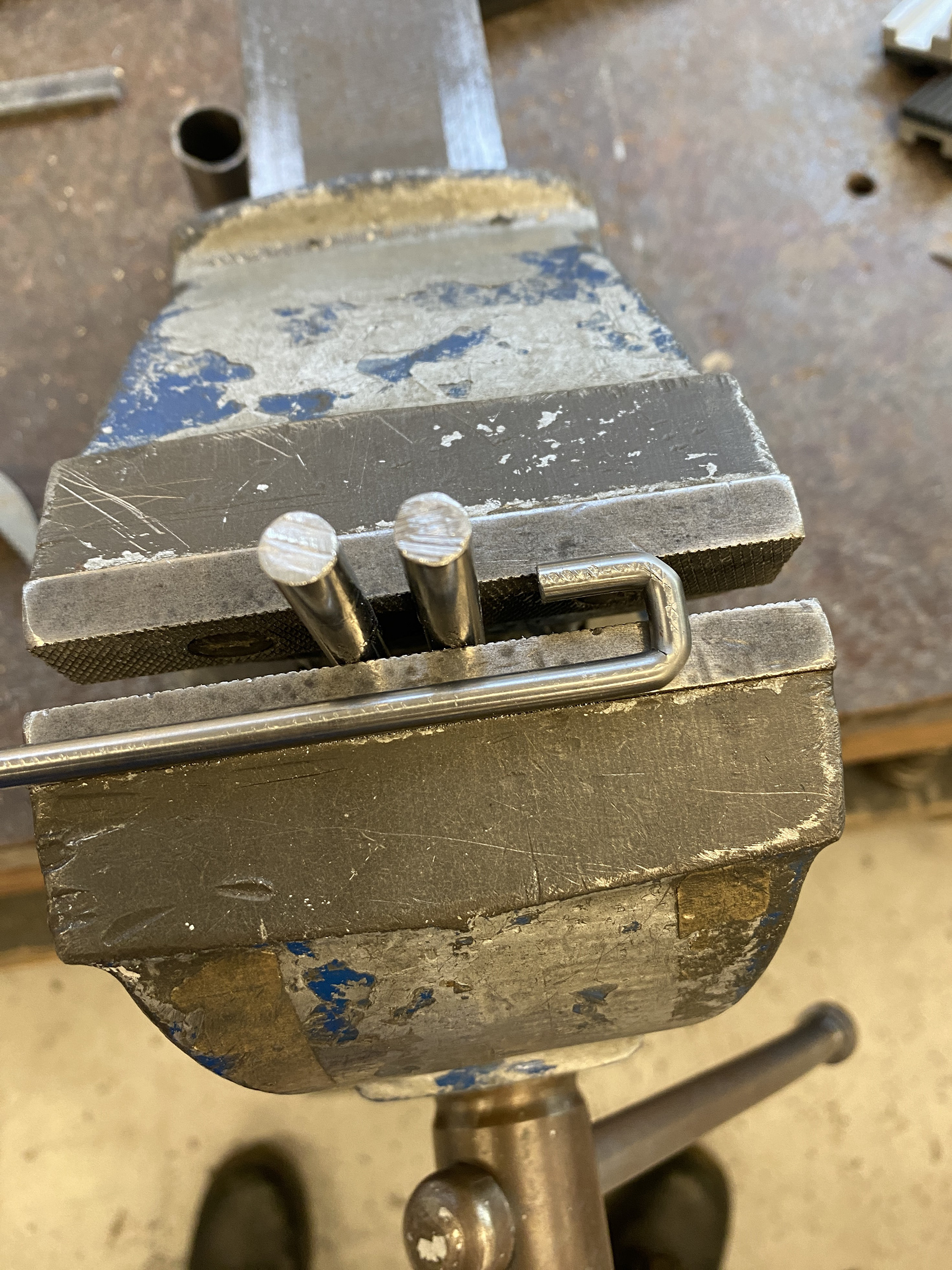
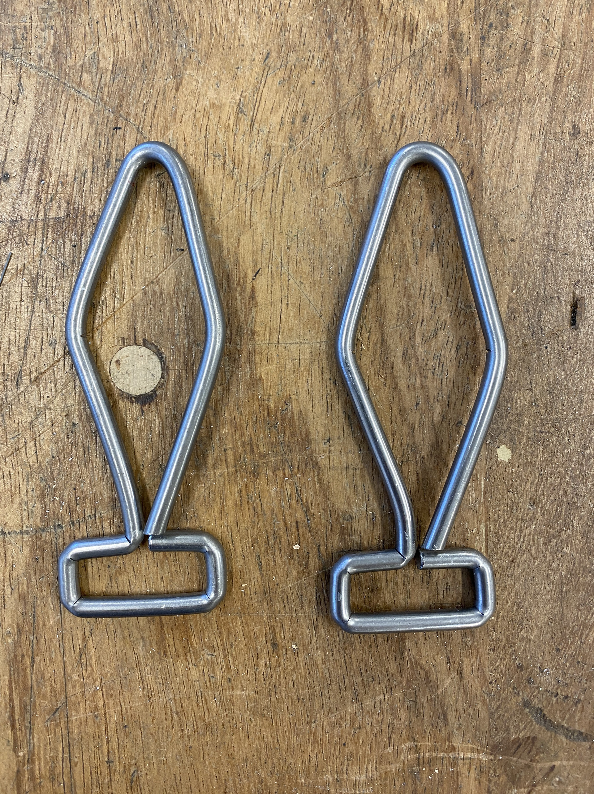
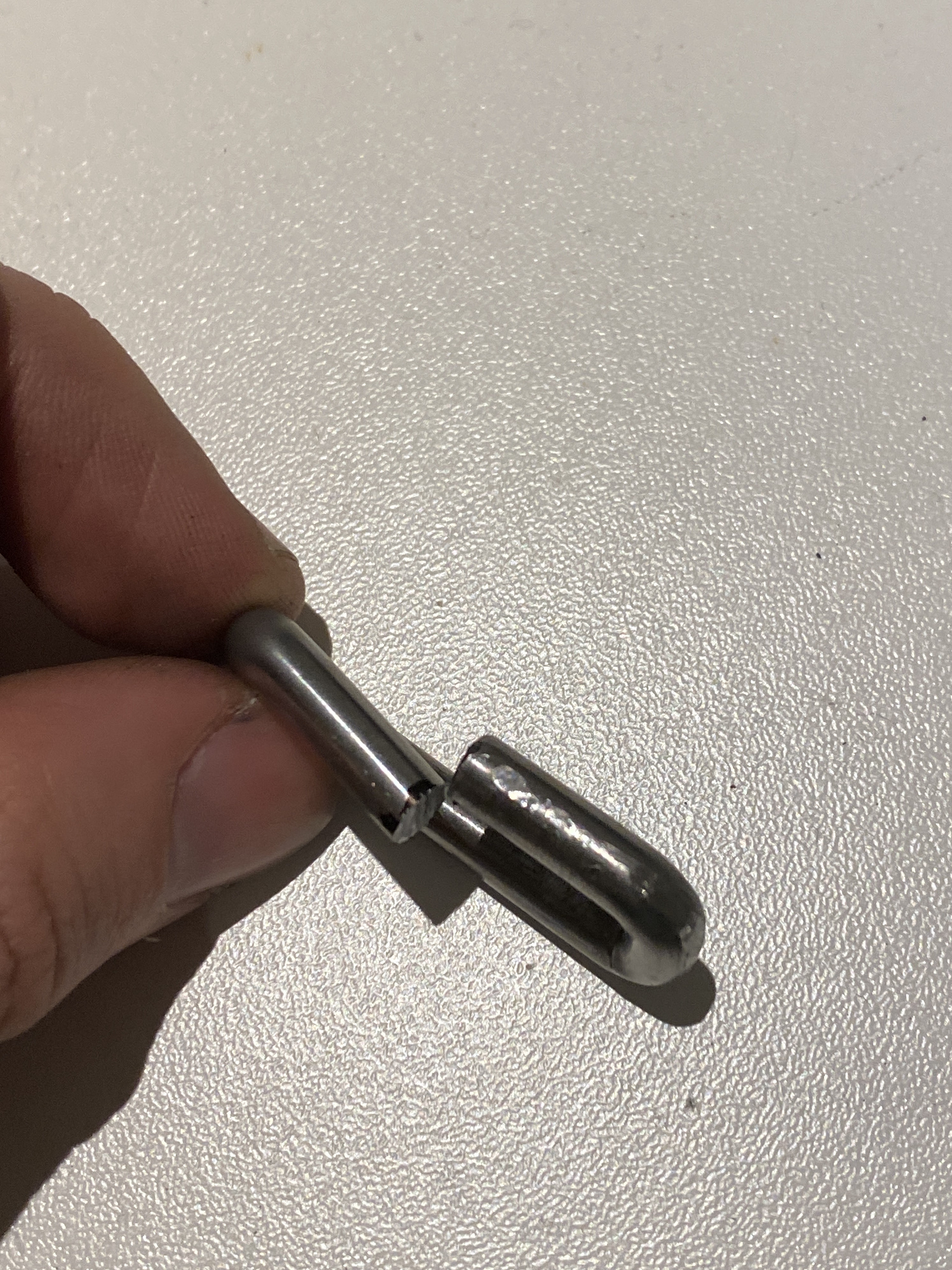
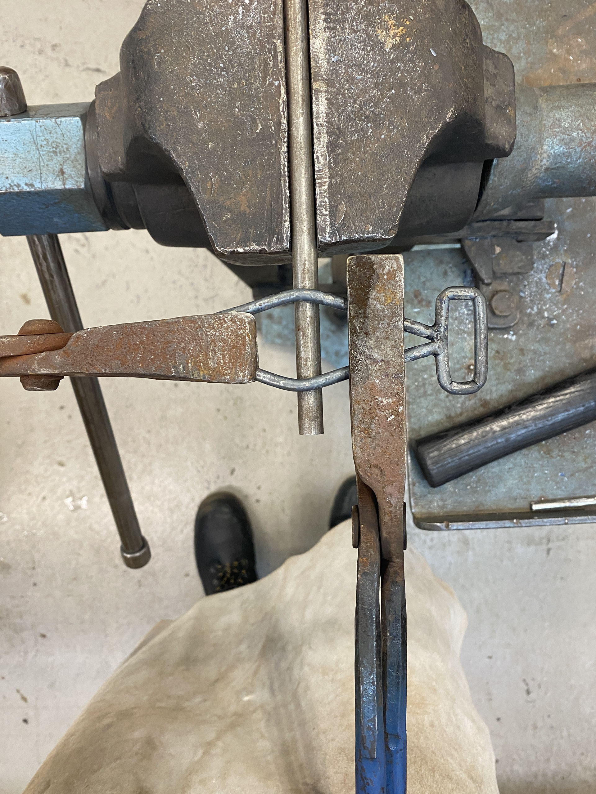
I piercing sawed off the excess rod and tested welding the joins. The spot welder couldn't bridge the gaps, instead melting the rod. I then laid some small tacks using the mig welder on top of a copper sheet so that it didn't stick to the steel benchtop. Finally, I used the torch to heat up the areas that needed to be bent to create the hook shape. I did this using a 10mm rod in the vies and tongs, referencing the 3D printed model for dimensions.
I feel that this process works but doesn't give a high level of control and refinement. The level accuracy is dependent on me repeating each bend and angle to the exact specifications, if one is off the rest will also shift. I think that there are areas for improvement and further testing.
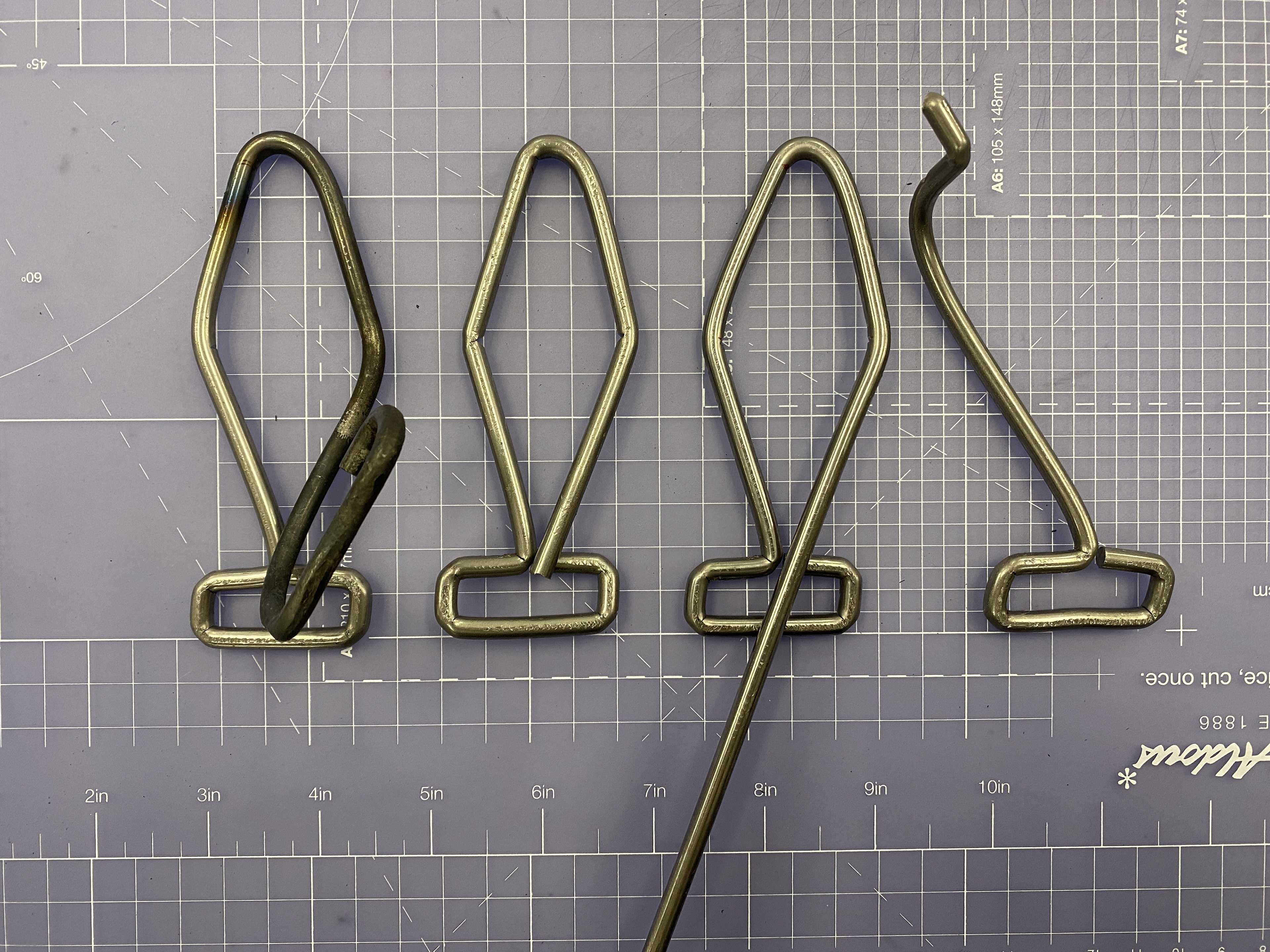
Redesigning the clasps

Reflecting on my previously clasp designs I realised that they were too complex to produce to a high quality. I would have had to cut and file the pieces to an exact fit and then carefully weld them together, which I don't believe that my welding skills and experience is currently at a high enough standard. Also, this would have taken many weeks to develop, which I don't have time to dedicate to one detail.
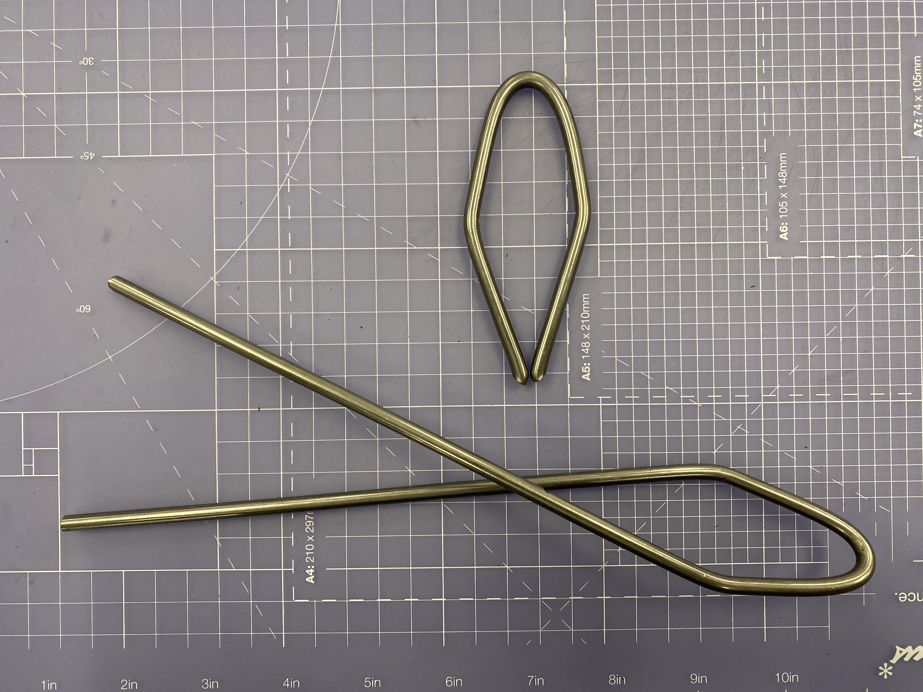
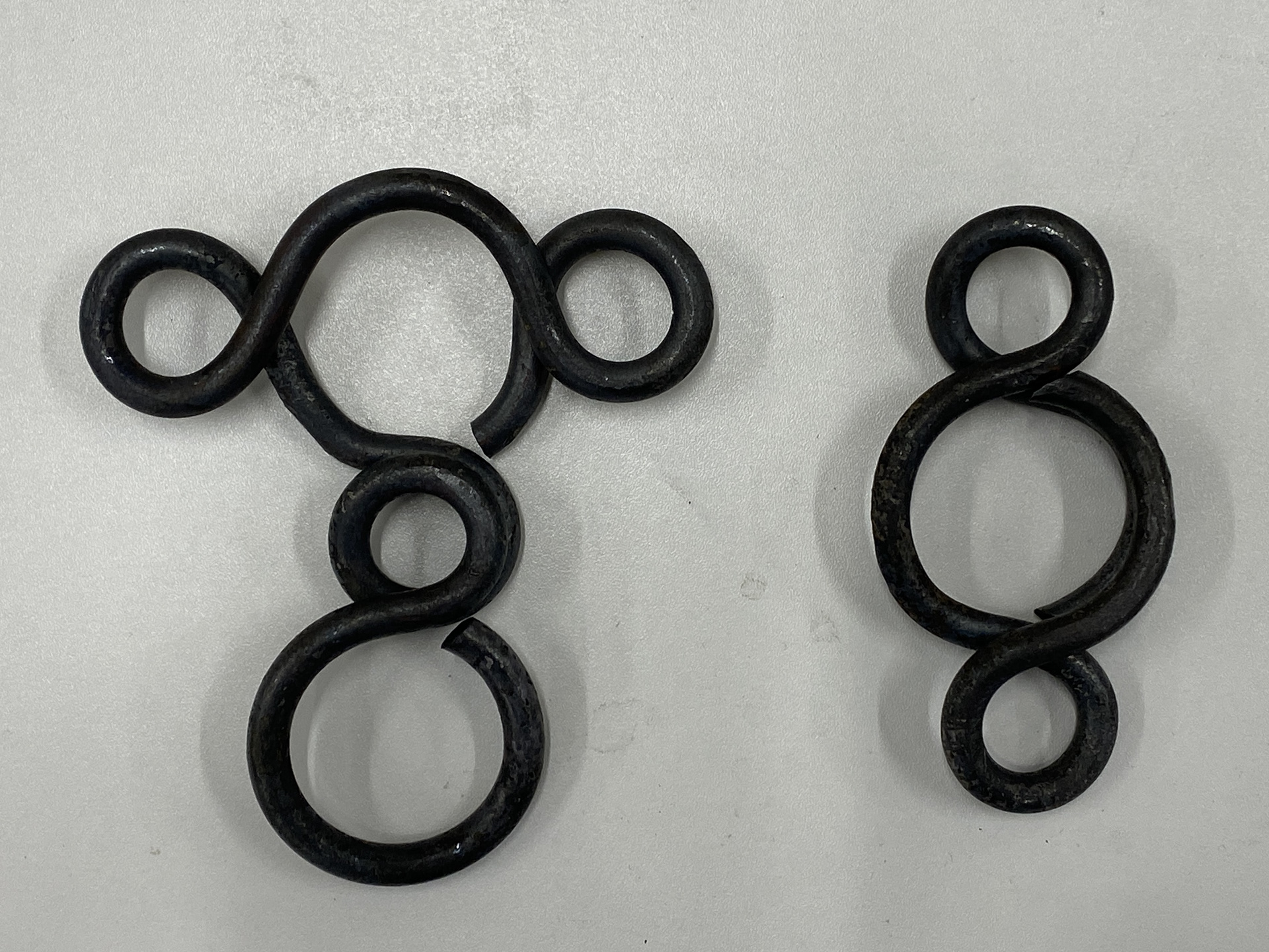
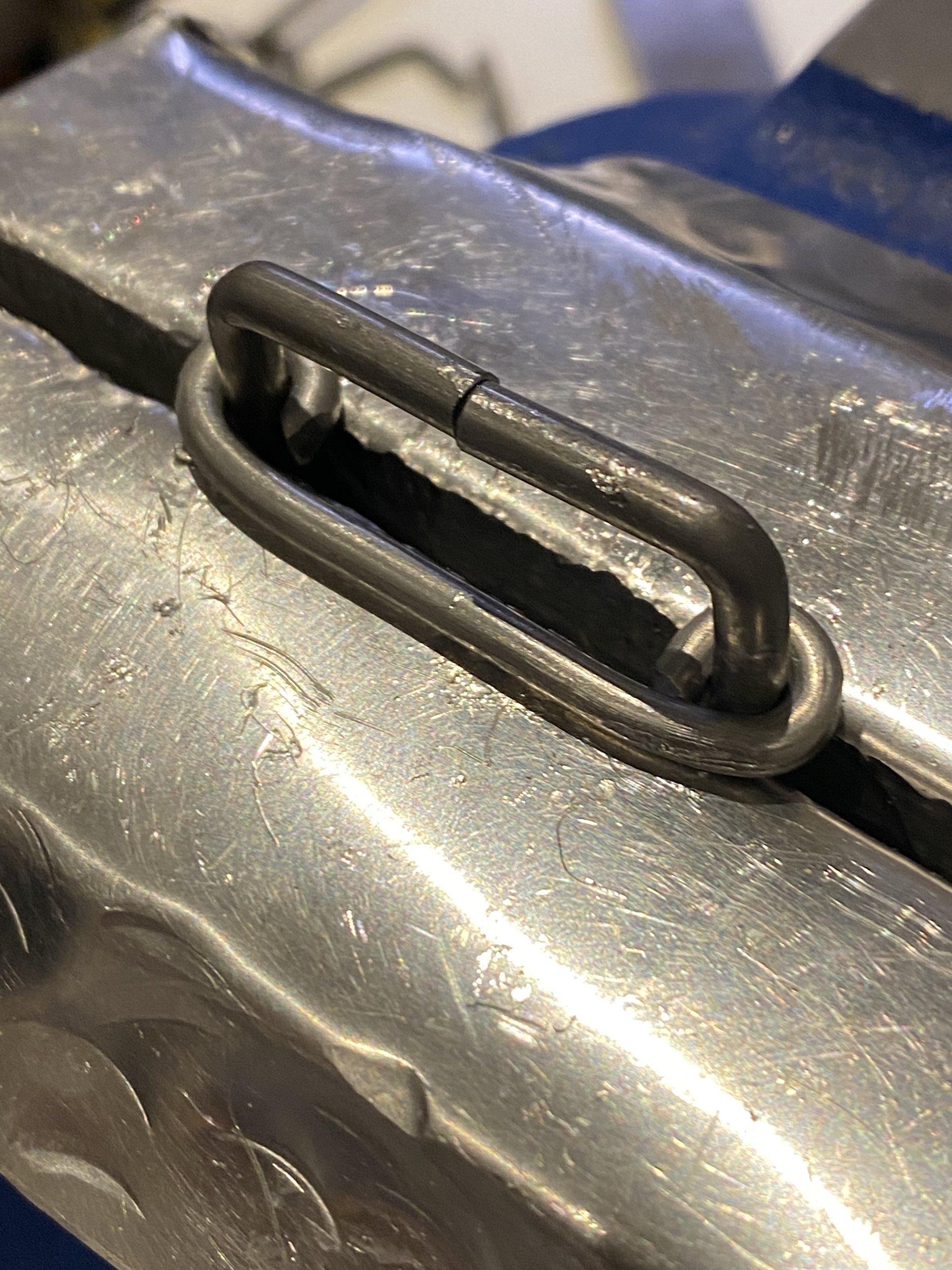
Therefore, I went and redesigned the clasps trying to keep the same concept of linking and the sizes of circles being taken from the chain. I used 3mm aluminium wire to rapidly prototype ideas and compositions. I focused on a system of continuous line, where I could bend the steel rod around different stakes to form the piece rather than welding individual components together. I chose the designs on the right due to their simplicity and functionality. The smaller circlers serve as attachment points for the buckles and the larger for the hooks to lock onto. I feel that the symmetry and rotation of the design mirrors the systematic weaving of the chain.
Forging the back piece

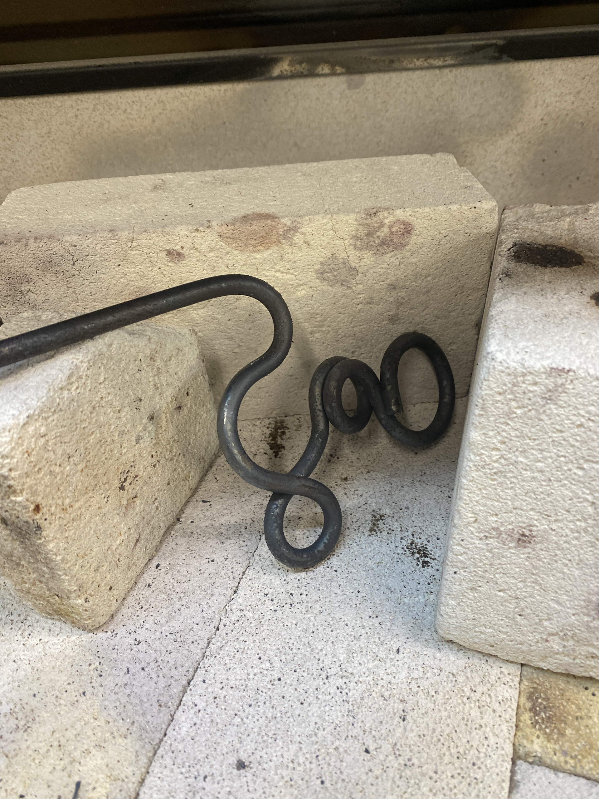
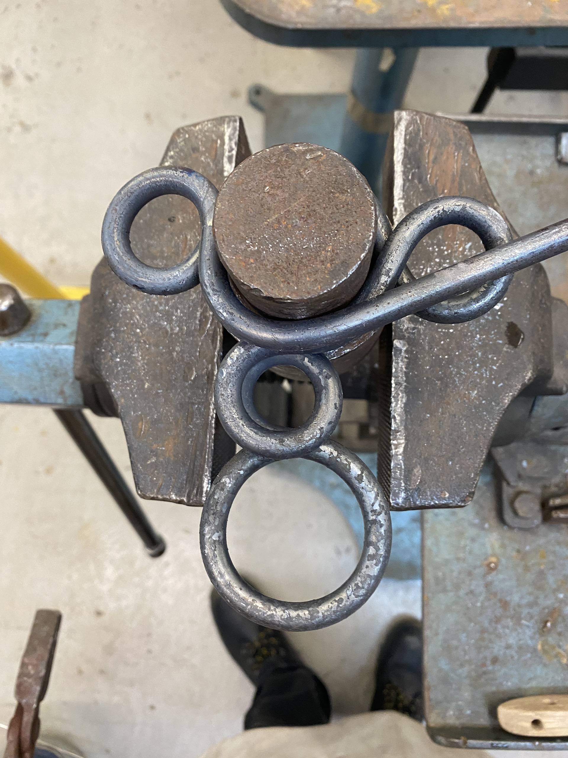
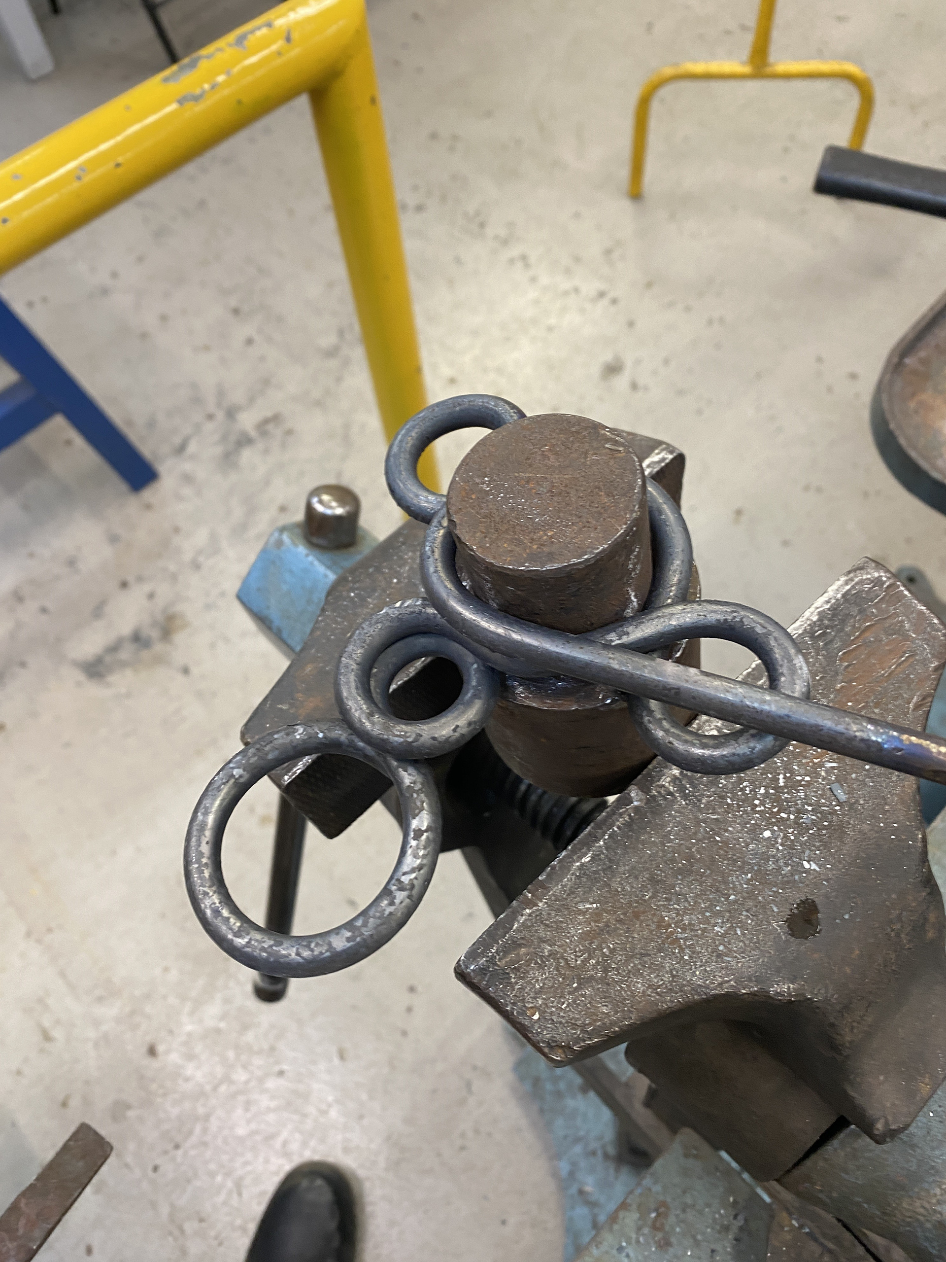
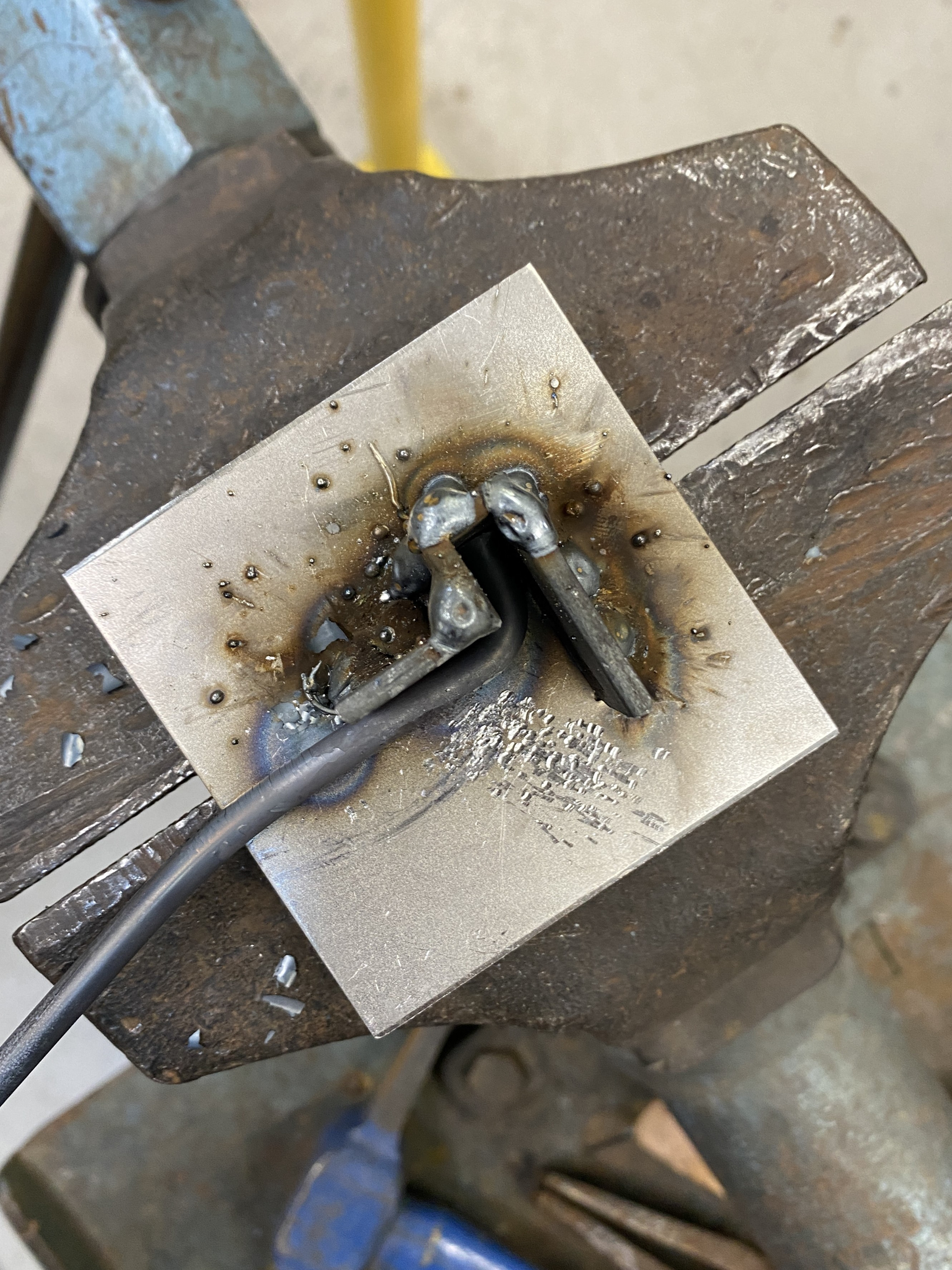
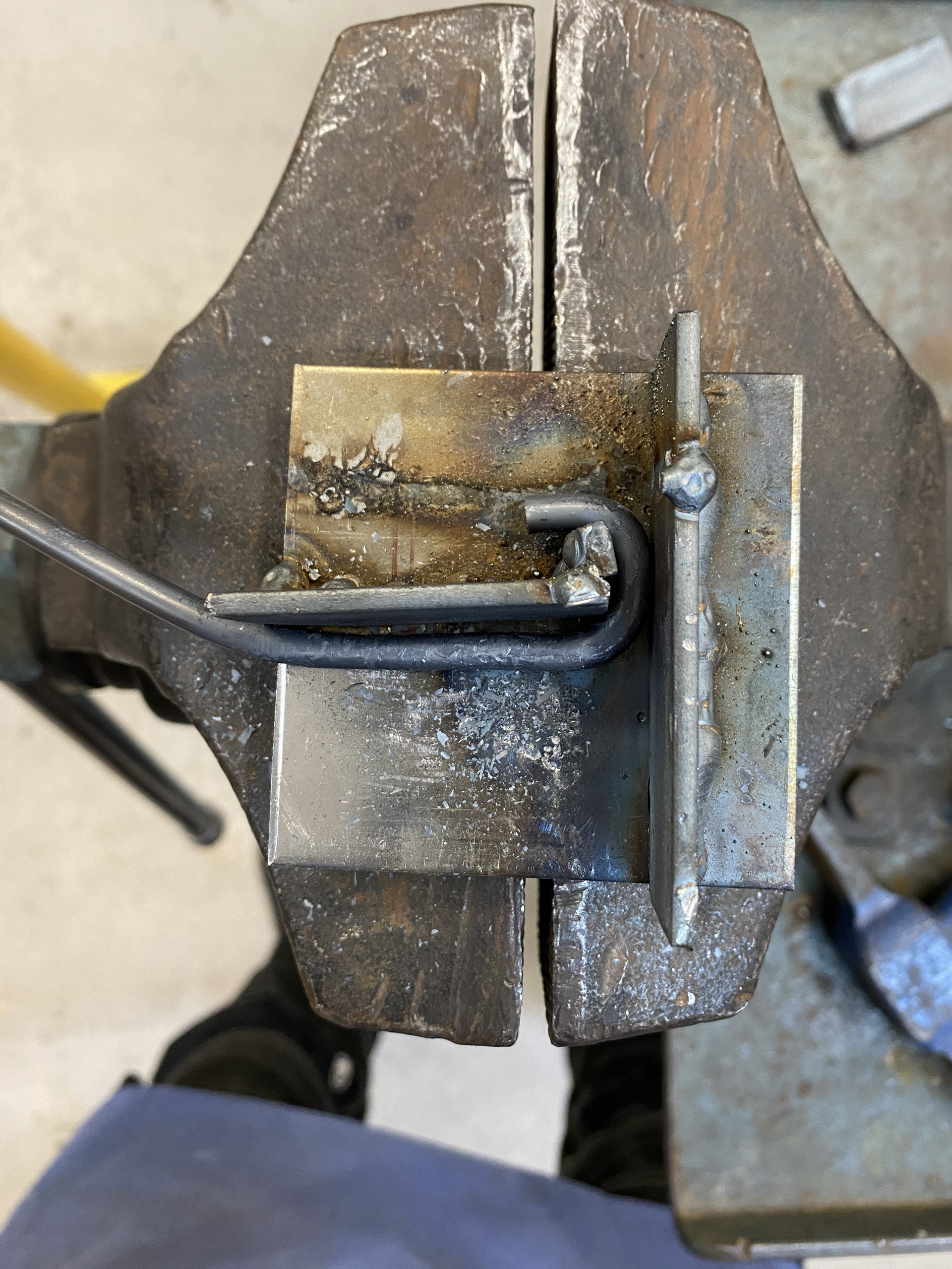
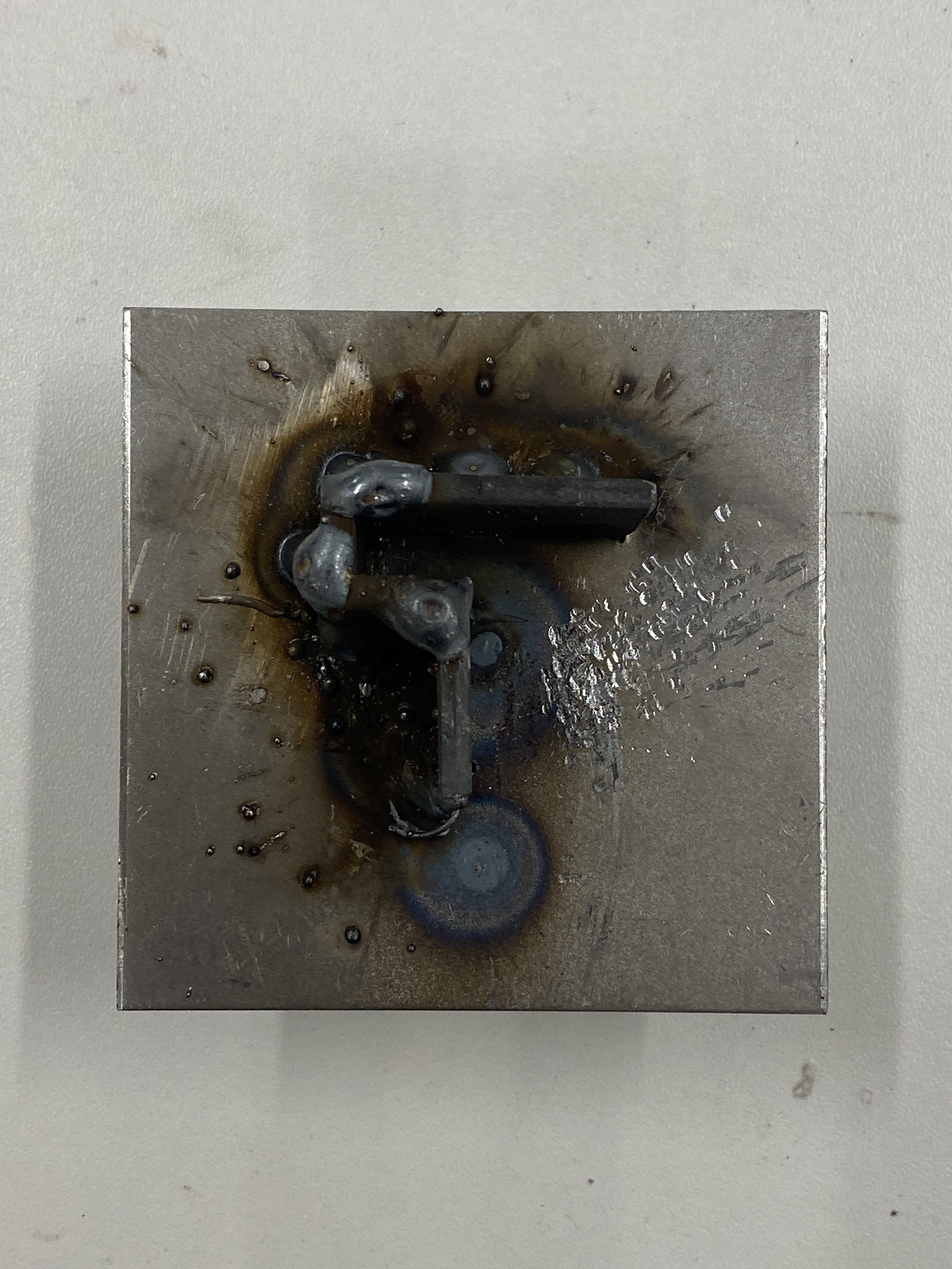
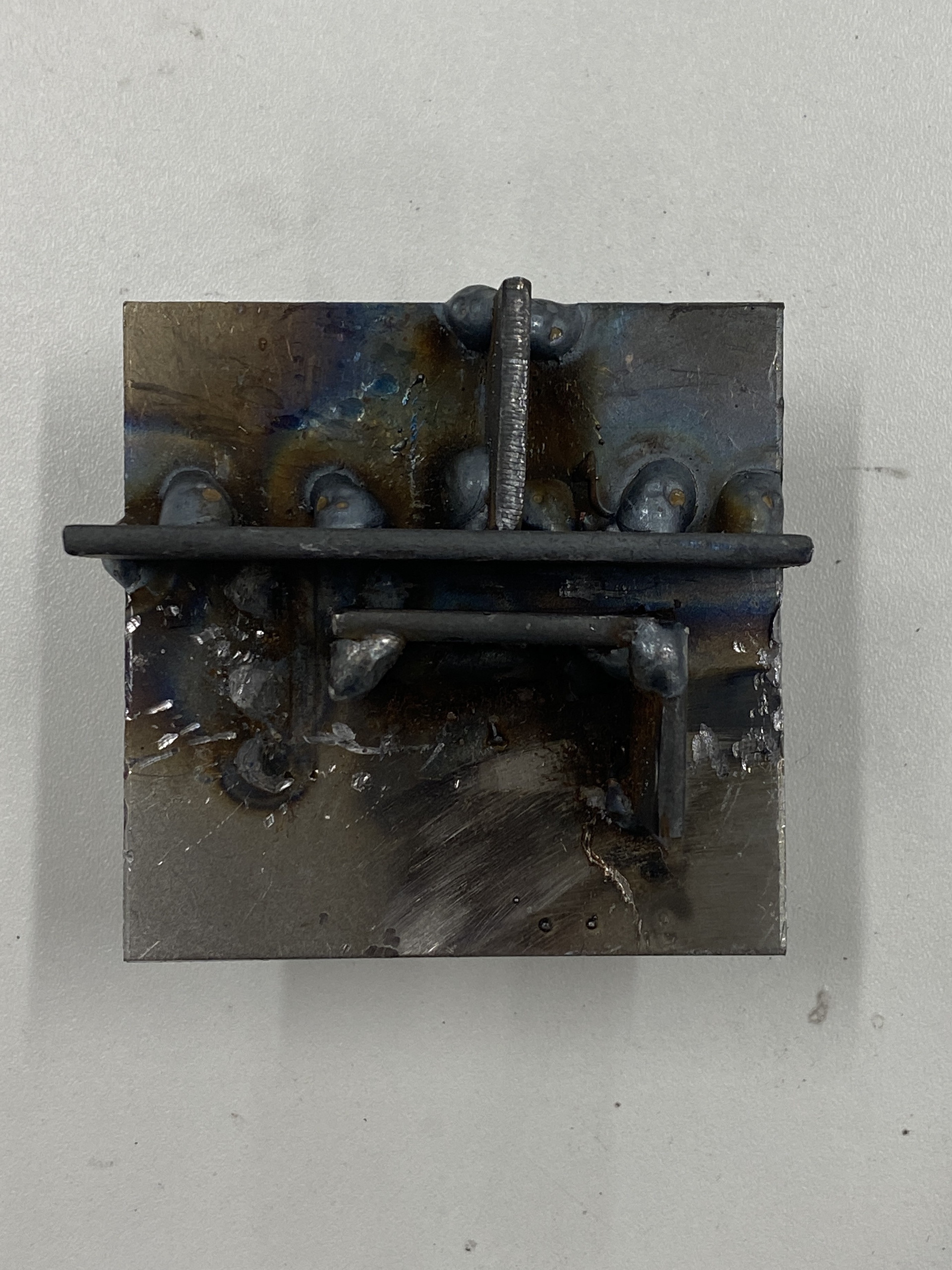
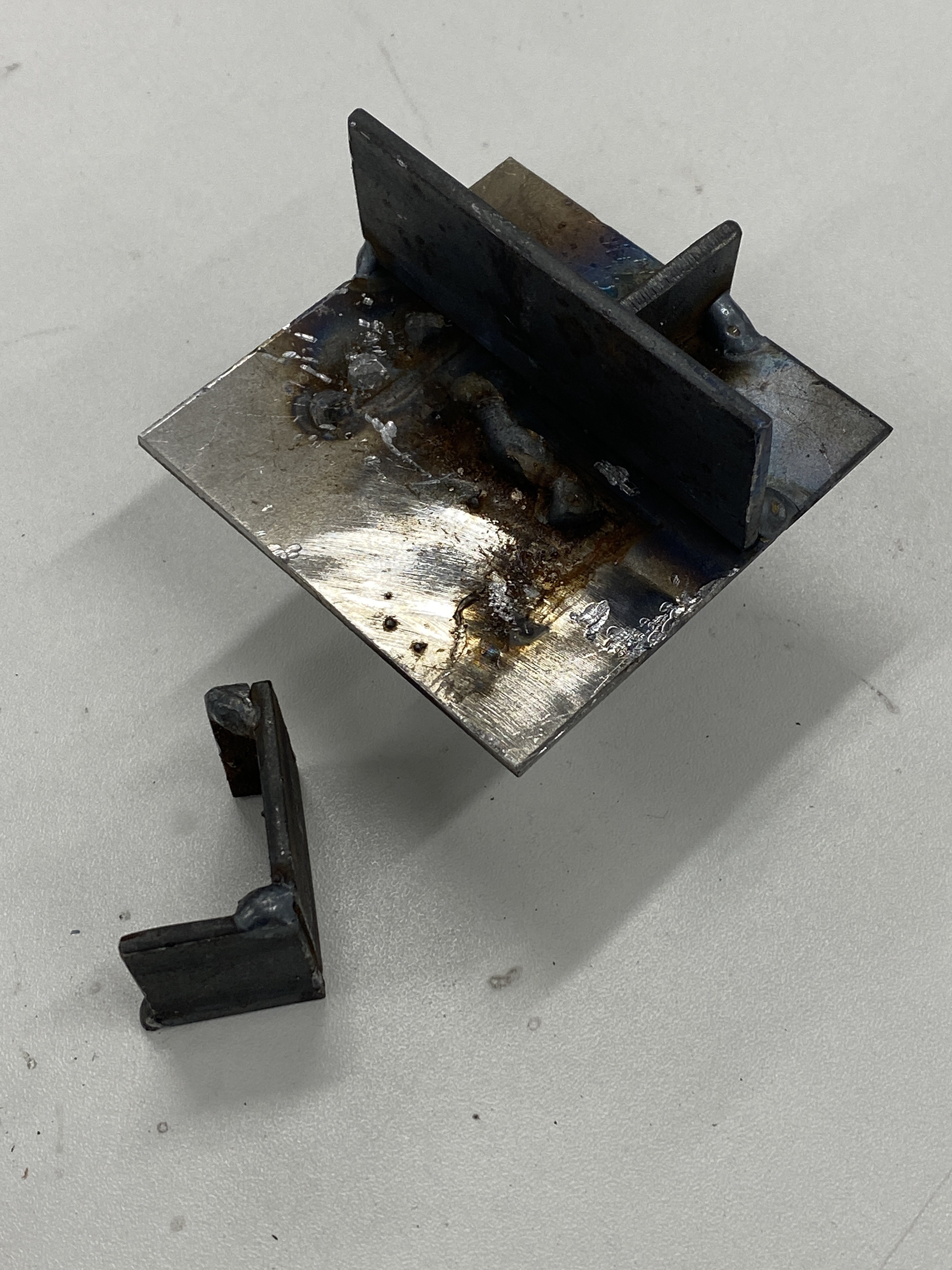
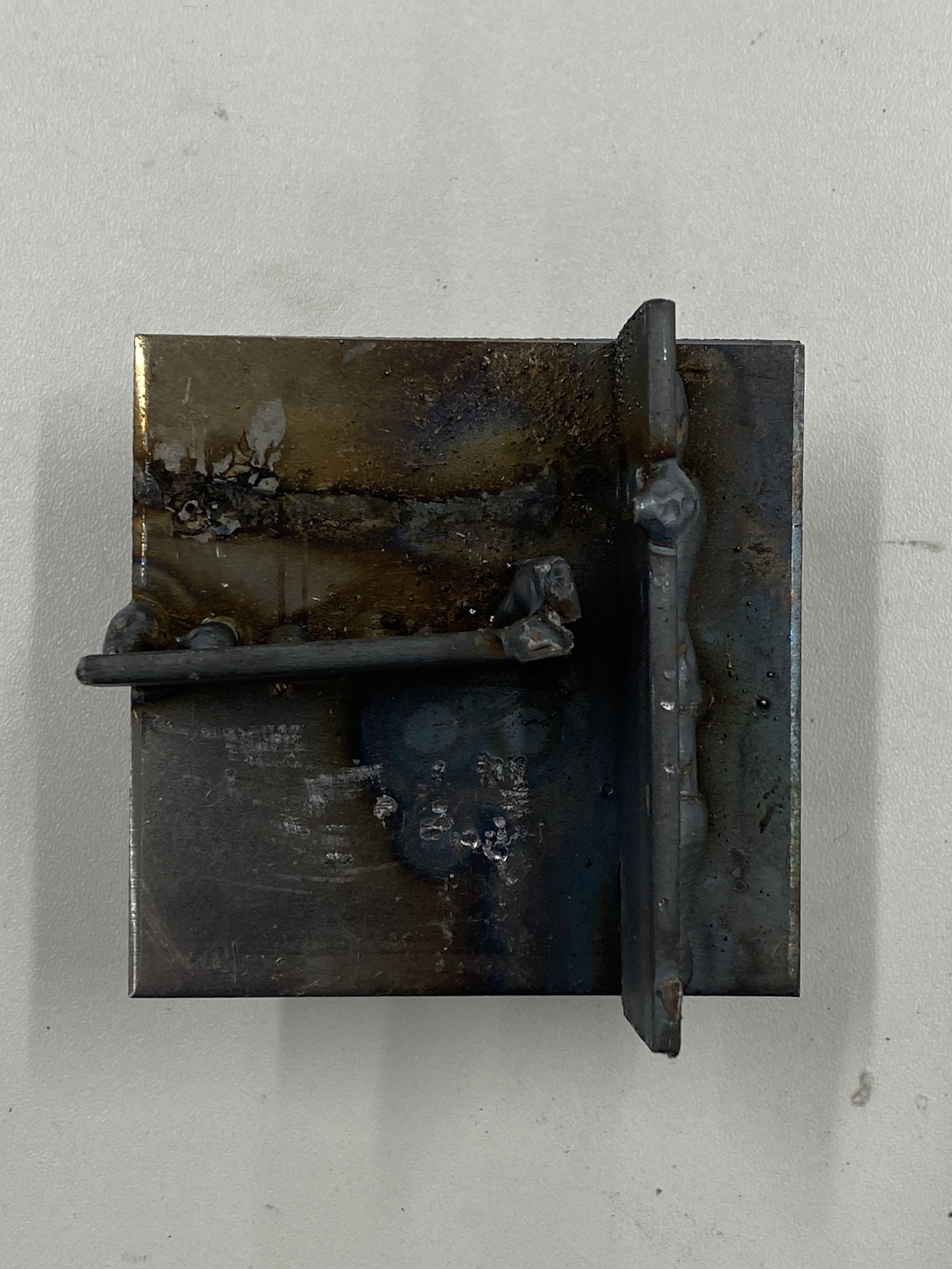
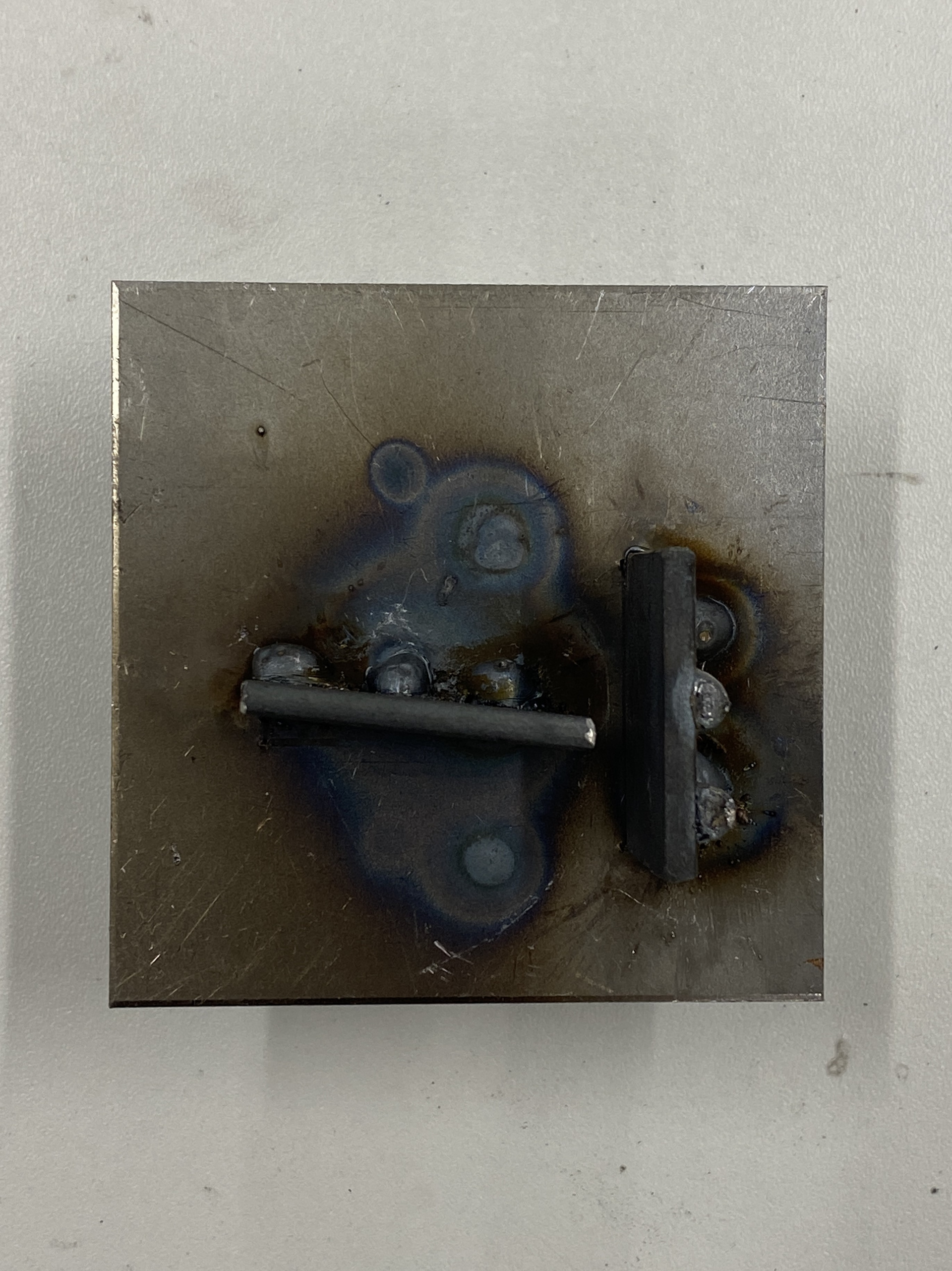
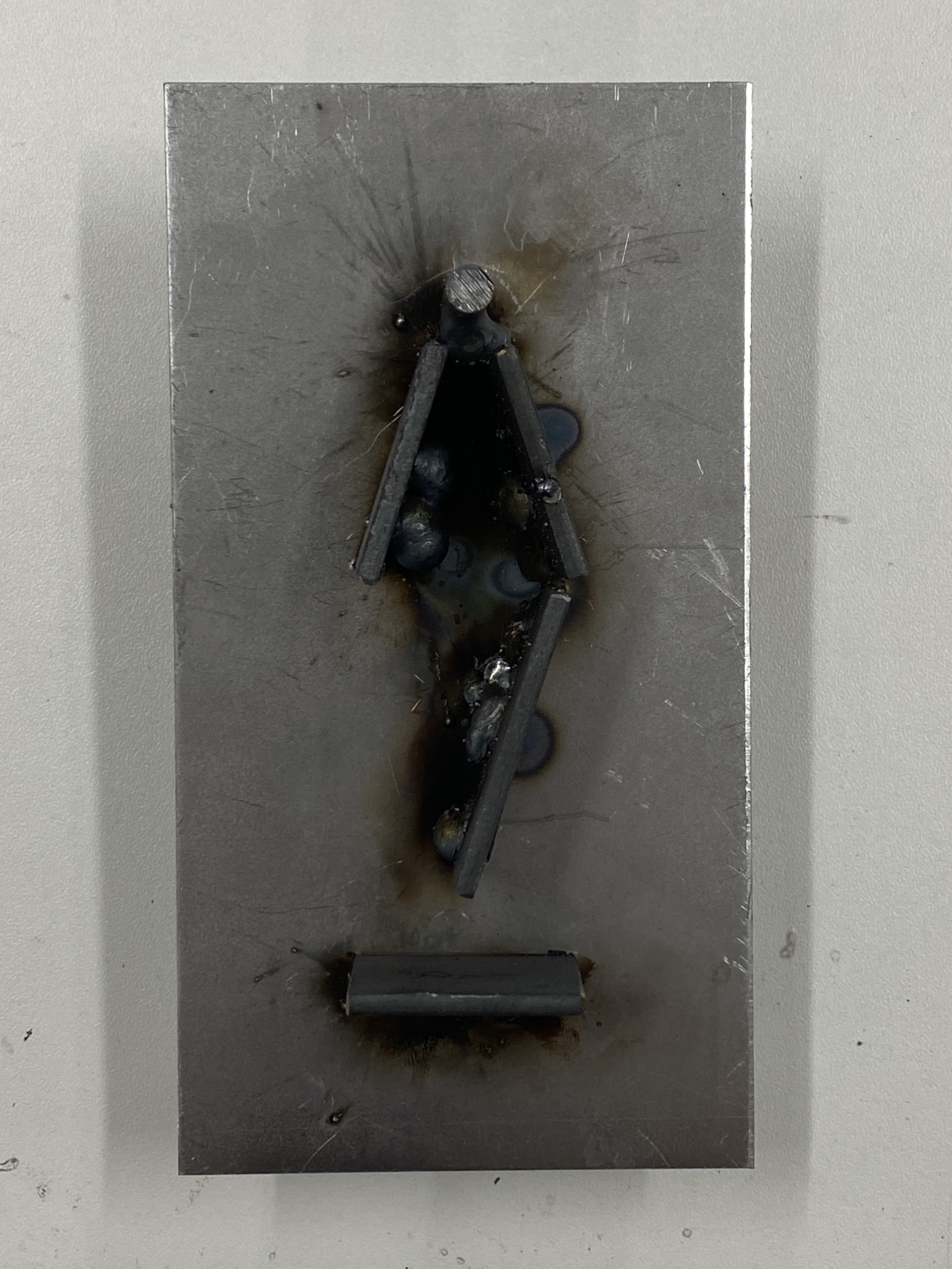
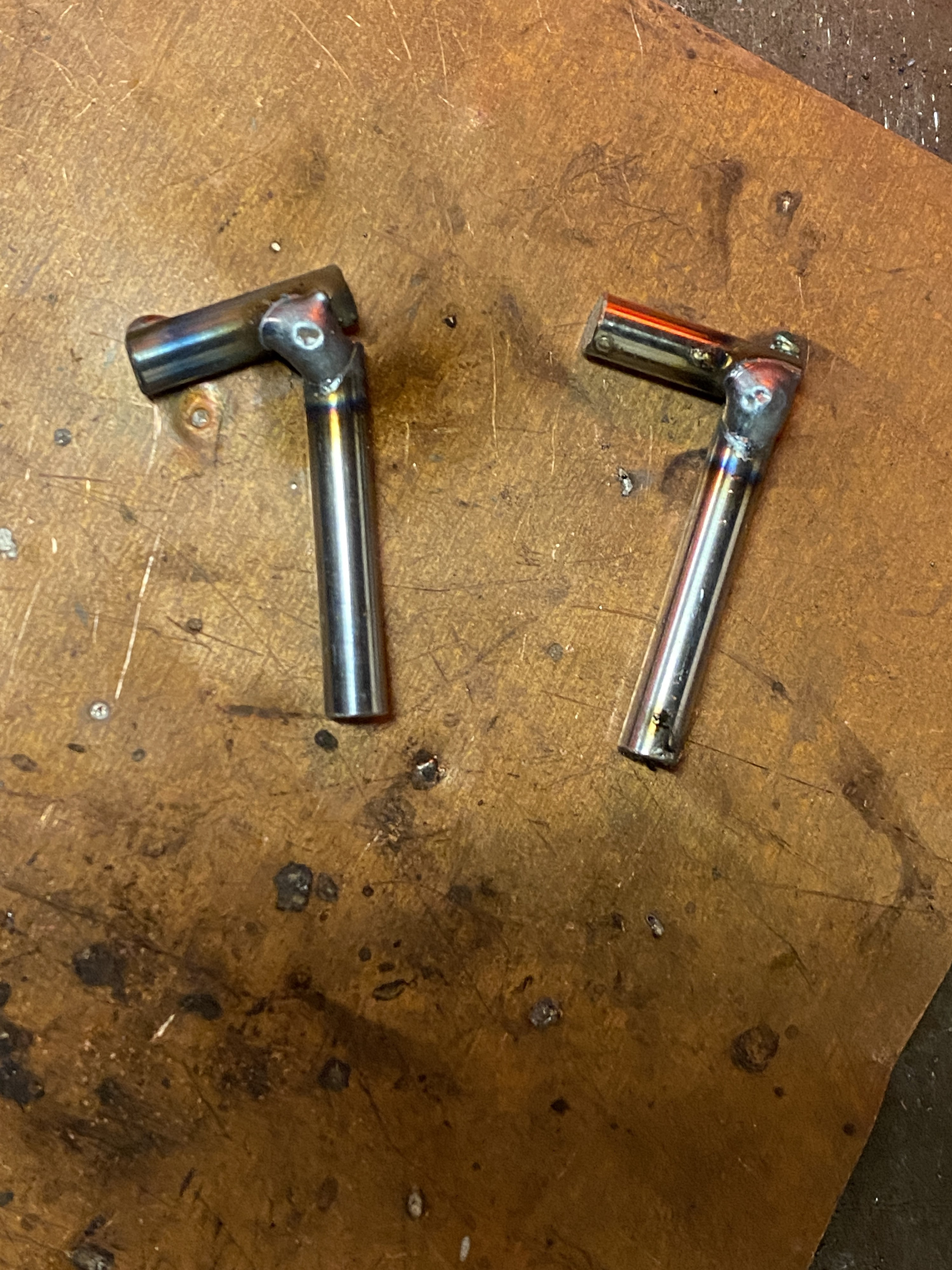
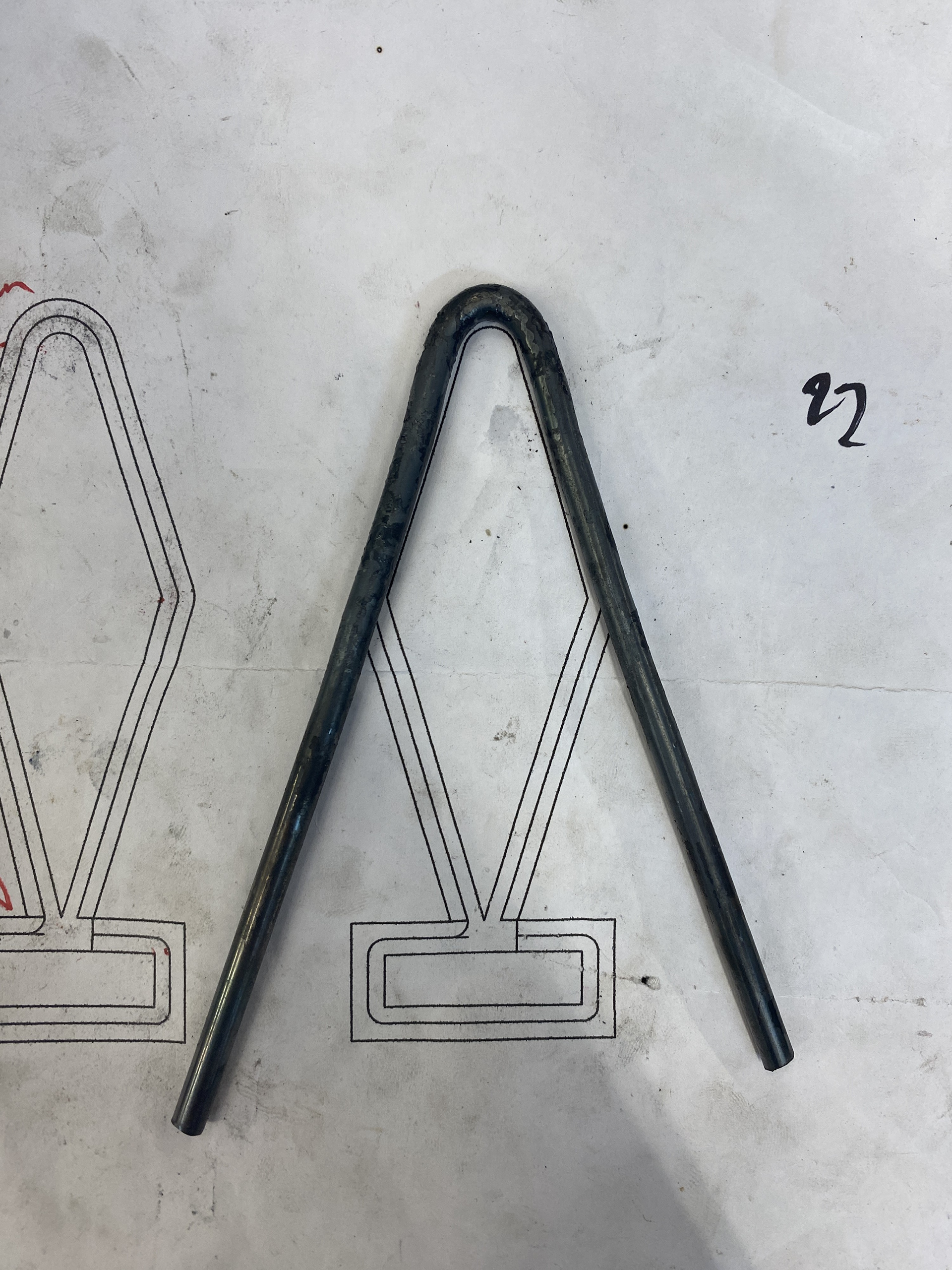
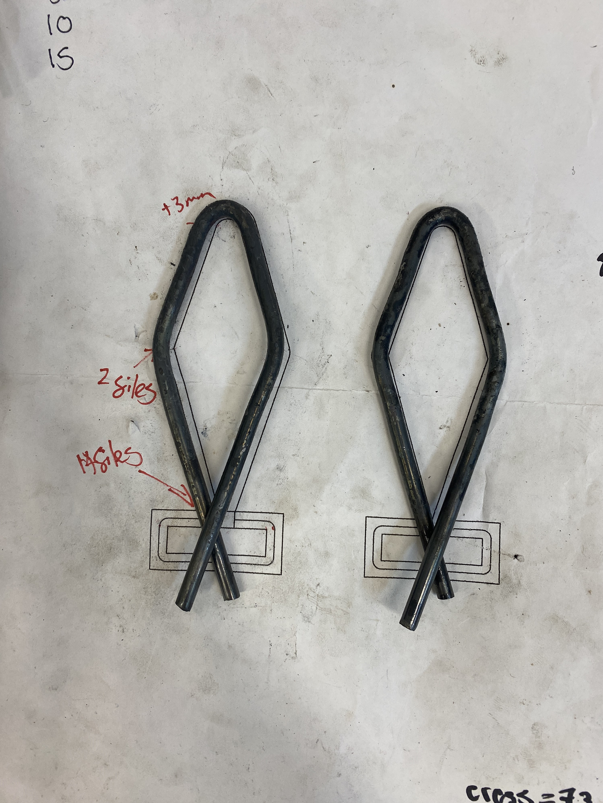
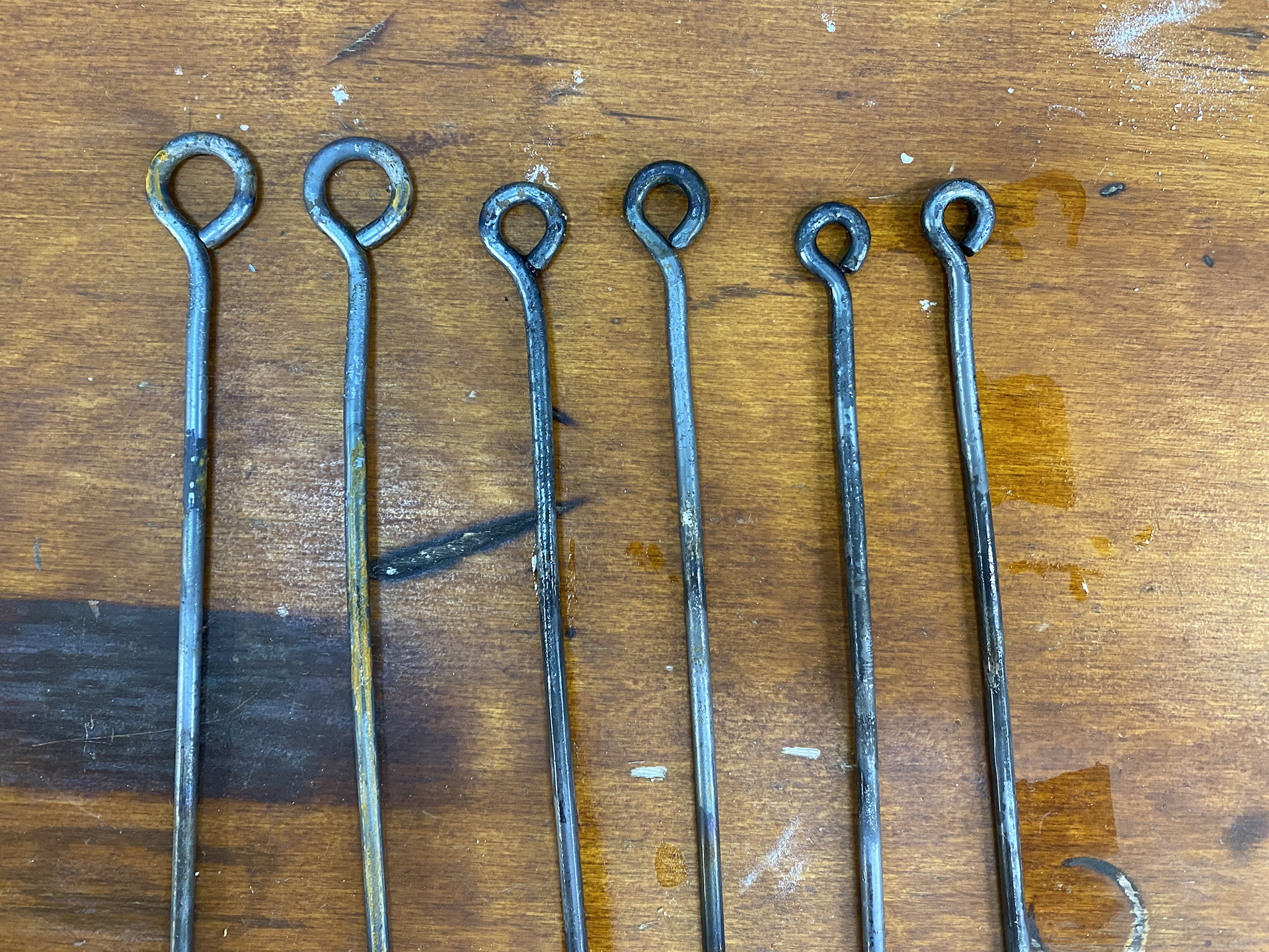
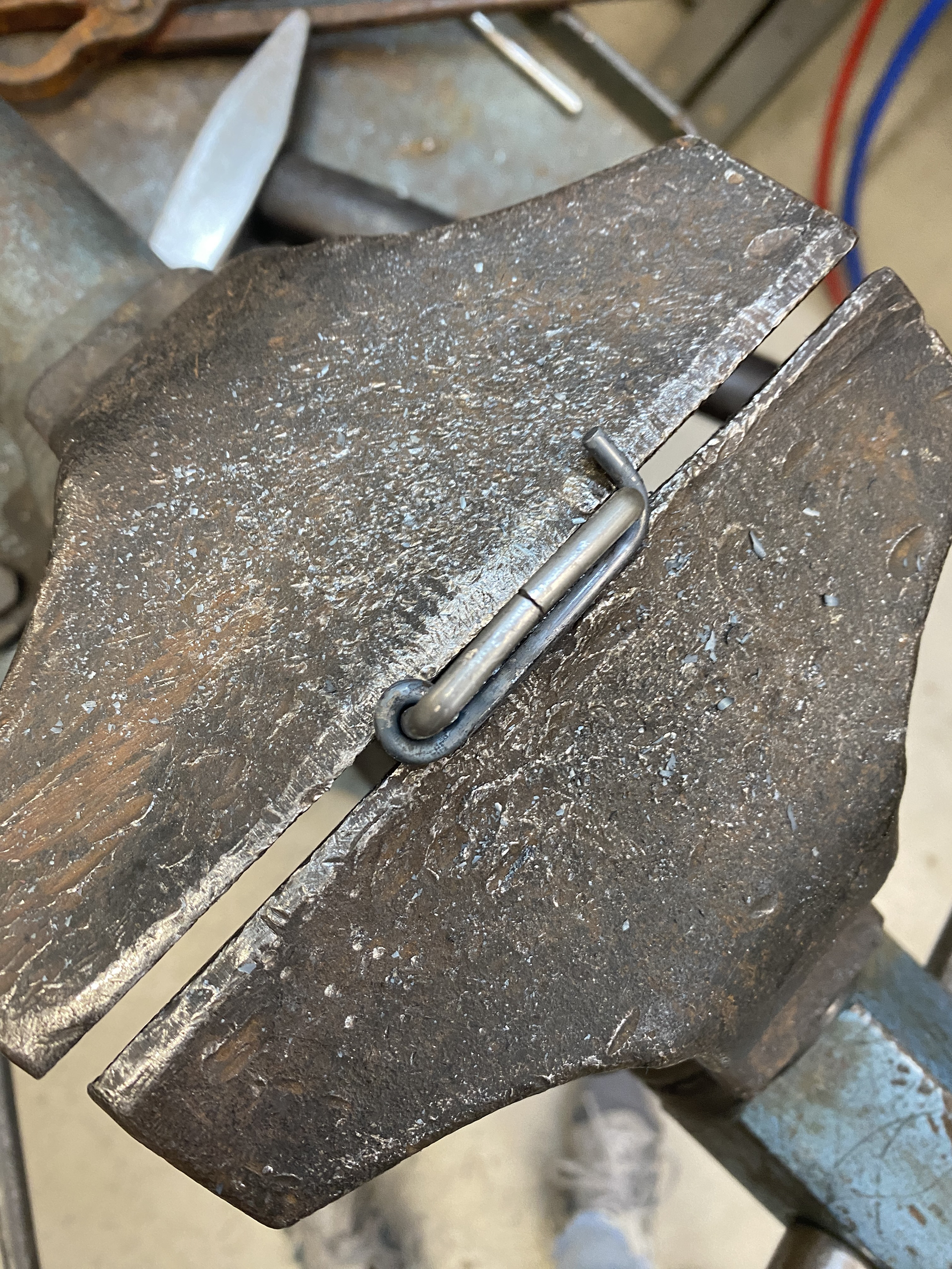
I used 8mm steel rod and bent it around the stakes I used to create the forged mail. I used a template and the aluminium model as a guide to the order and location of the bends. I found that quenching and heating in specific locations using the torch helped me to control the bends and keep the symmetry. I cut the excess off using a piercing saw, then heated and hammered the pieces flat to close them. I think that this last stage could have been done cleaner as the gap is a little larger than I had intended and draws the eye away from the design. I need to work out a better cutting process to get a tight line up of this type of connection moving forwards.
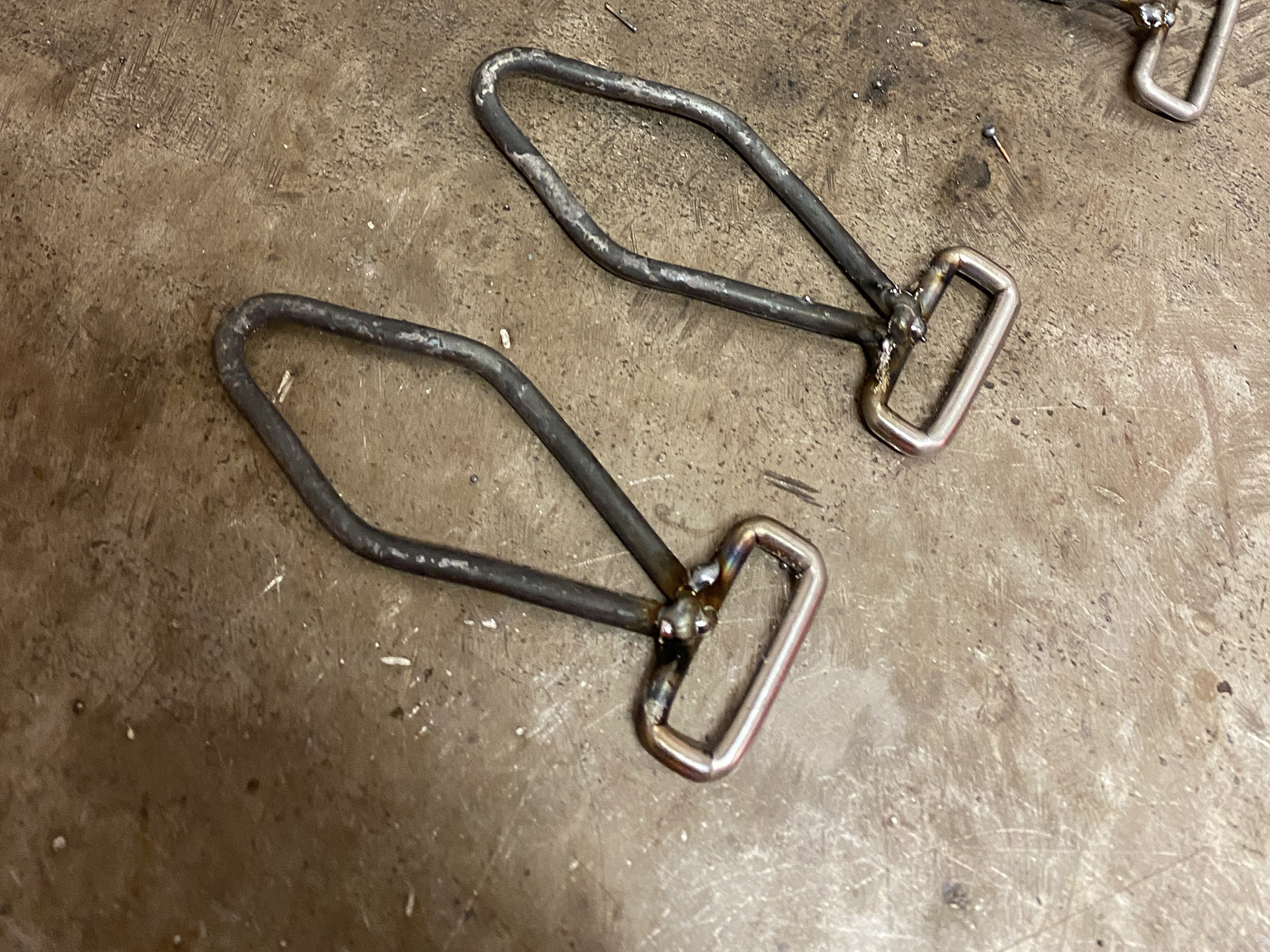
Originally, I had planned for the two claps to be joined with a strip of leather and hardware. However, when inspecting them on the mannequin I found that there wouldn't be enough room for this, and a connecting piece was needed. I modelled some ideas using 3mm aluminium wire, focusing on a simplistic design, not to distract from the rest of the piece.
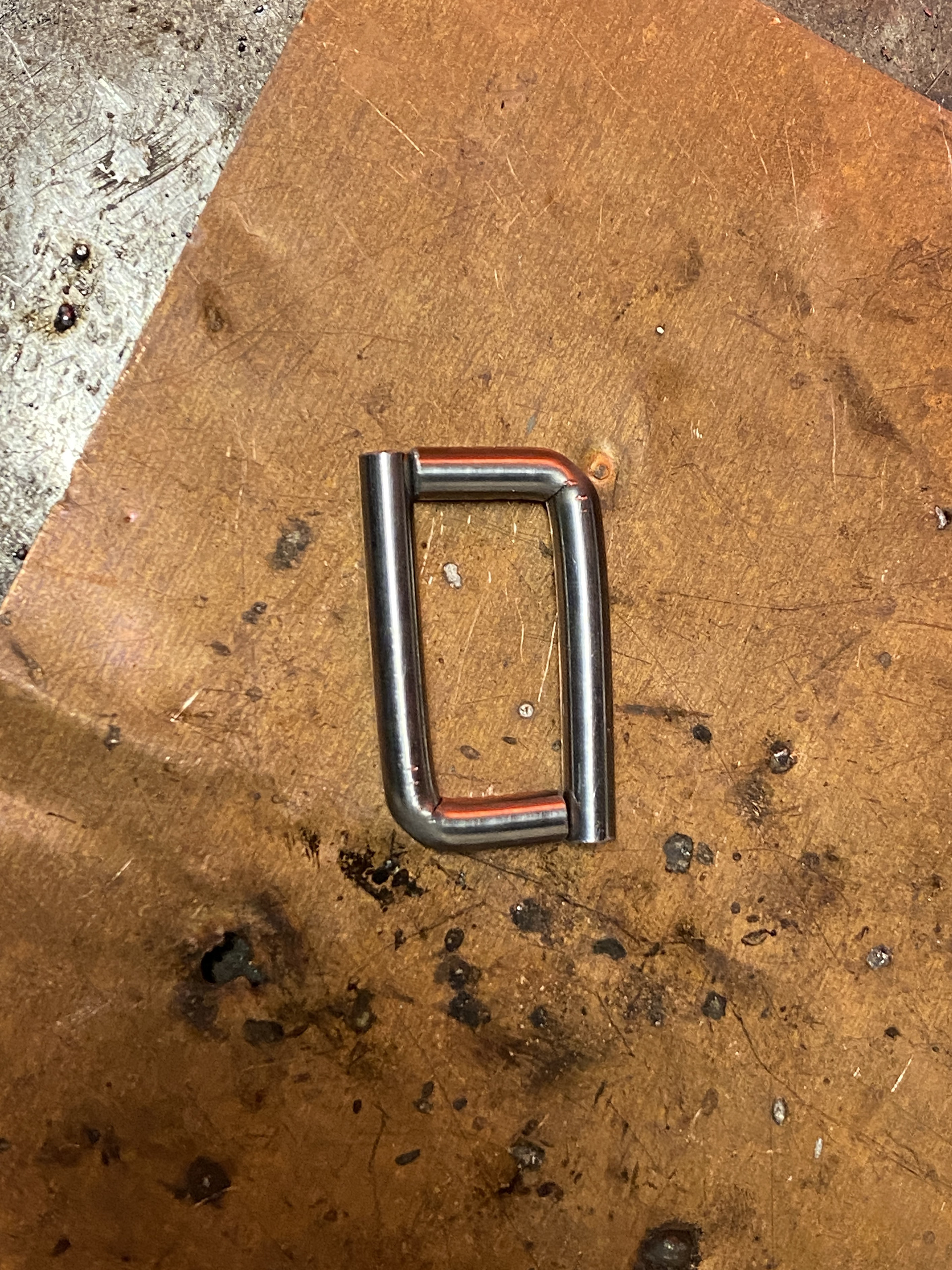
I found that the best design was two circles with a straight connecting bar in between, this held the two pieces in a set distance apart while allowing them to shift and adjust with the movement of the body. I had to increase the middle bar length, as a shorter (as modelled in aluminium) bar made forming the eyelets too hard on such a small scale.
Designing and producing rest of the hardwear
I laid the piece out and ladled the different areas and connections that needed additional hardware.

Through testing I found that I needed 3 different sized eyelets connected to the rectangle rings. I chose a 12mm internal diameter eyelet for the 8mm wire diameter, 8mm internal diameter eyelet for the 5mm wire diameter and 6mm internal diameter eyelet for the 4mm and 2mm wire diameter.
In my hardware designs I had incorporated a slider buckle so that the length of the straps could be adjusted and the position of the piece on the body altered. I mocked up a quick design in aluminium wire and fabric scraps to understand the mechanism. I then tested different length of buckle so that the leather could easily be adjusted but also not slip through when being worn. I found that the 20mm worked the best.
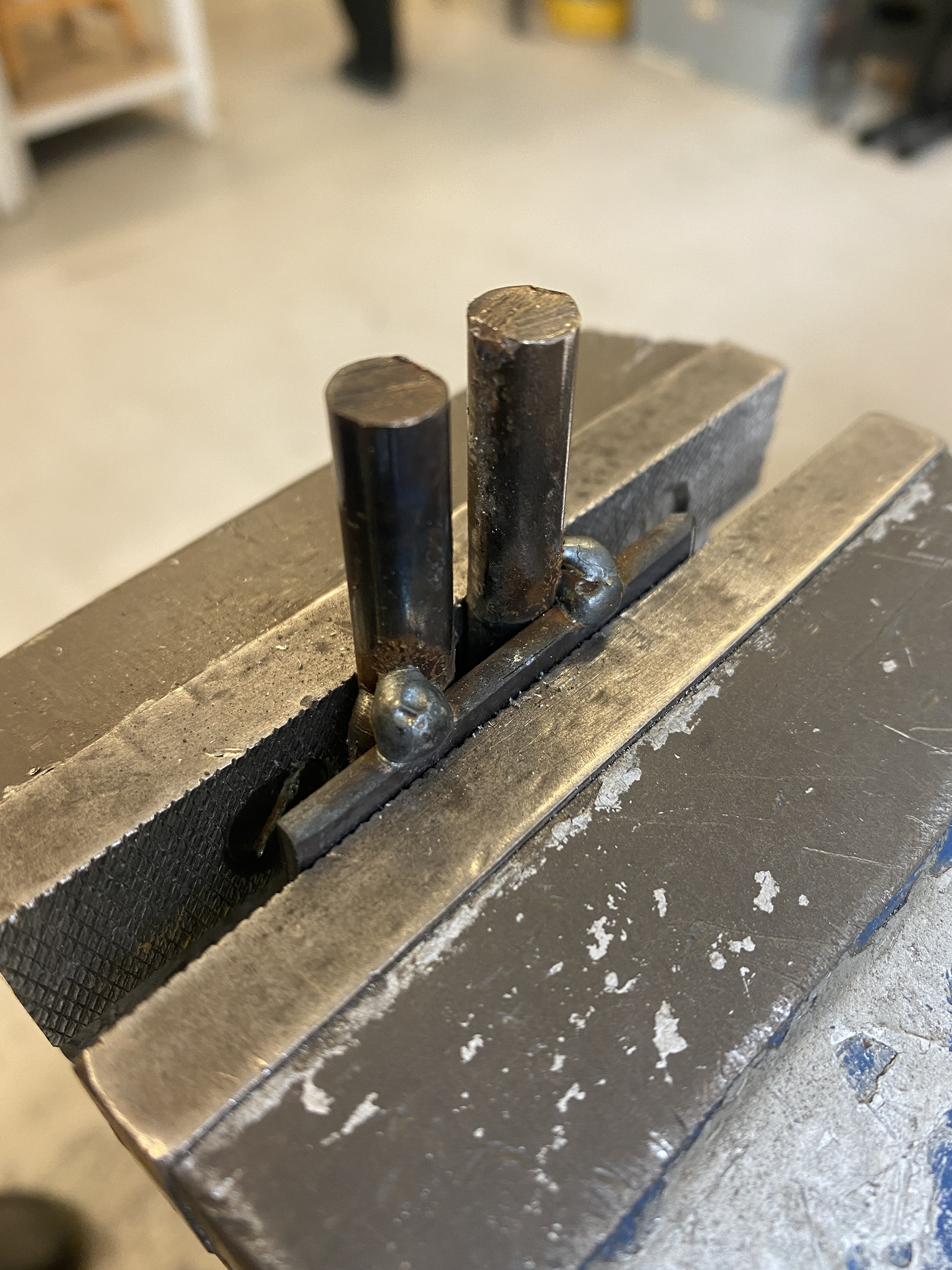
To produce the slider buckle I bent the 4mm steel rod into a rectangle using the same process as the v shape hooks. I then bent a 3mm rod around two pieces of the 4mm steel rod that were locked in the vice 30mm apart, mirroring that of the rectangle. I cut the excess rod and then slid the central bar into the rectangle.
This method had multiple flaws, the main problem was the consistency and repeatability. I think that the way I was measuring and marking out the bends and area to cut the grove into with the file wasn't accurate enough. Despite using a calliper to measure the distance, I used a wide marker to draw on the filing line which caused minor inconsistencies. Any miss marking caused differing lengths and angels resulting in uneven rectangles.
Another problem was forming the middle 3mm rod. The way I secured the pins that the eyelets were bent around caused additional inconsistencies. The leg vice's jaws aren’t completely parallel meaning that there was looser grip on one of these pins. This caused them to shift changing the 30mm distance. Also to form the second eyelet the rod was wound over itself and then cut. This meant that there was a gap which varied in size and needed closing.
To produce the eyelet buckles I forged out the differing sized eyelets first, then bent the rest of the rod using the same process as the v shape hook. The forged eyelets were uniform and symmetrical, suggesting that this method would yield consistent results. However, when I went to form the 90-degree angles to form the belt loop the steel didn't bend cleanly at the weakened filed point. The forging process must have changed the malleability of the steel. This resulted in loose curves rather than tight bends. I tried to counteract this by using pliers to focus the bending force closer to the corners, but this wasn't that effective.
These components were done in a rush and made to a standard of practicality over quality. I had to finish these in time for the collaborative photoshoot with Lauren Broxton. Reflecting on the outcome of the hardwear, I was not happy with the results as the ununiform and poor finish brings down the quality of the whole piece. Therefore, I have chosen to redo these elements.
Reworking the hardwear
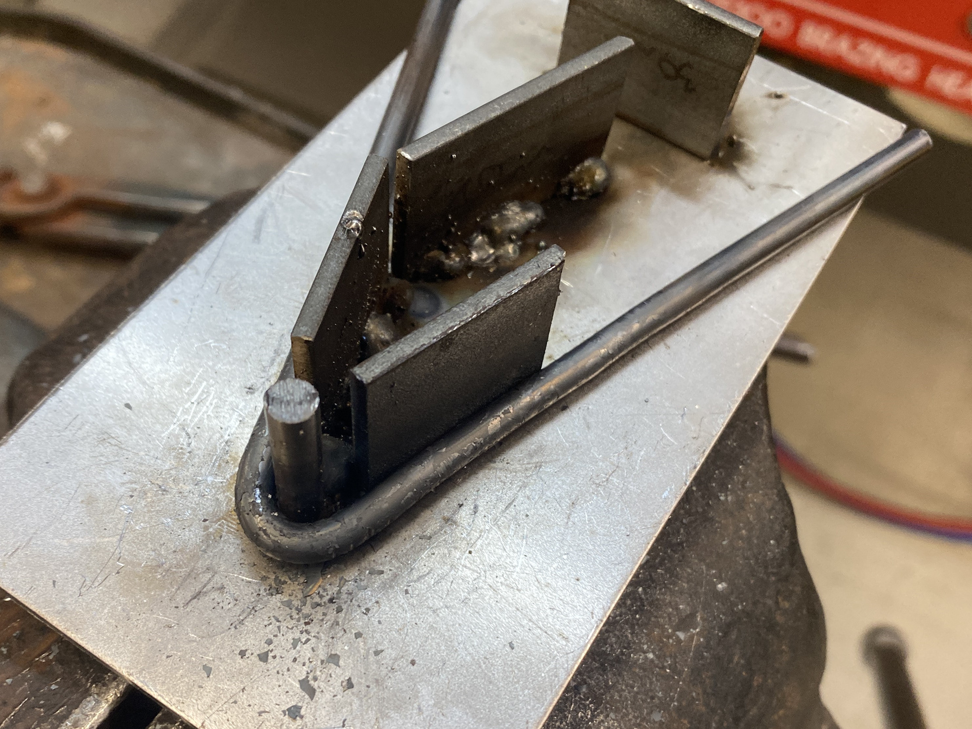
As most of the inconsistencies came from bending the rods by hand, I tested cutting each side and welding it together. I cut the pieces to length using a hacksaw then ground 45degree mitre joints using the linisher. I found that my first attempt was close, however the lengths were slightly off causing the shape to shift into more of a rhombus. I tried welding the pieces together and found that there was no real way to secure so small a piece and thus they moved about. I think that with the machines that we have this would be too difficult to create repeatable forms.
I then tested bending only two of the corners and welding the others. This was to avoid the difficult bends relying on putting force on the smaller sides of the rectangle that tended to slip in the bending forks. This method was quick and easy to create the rectangle, but the welded areas needed lots of filing to achieve a rounded and uniform shape. Additionally, the pieces were hard to secure whilst welding and therefore the piece was uneven.
One takeaway from this test was the development of the bending fork. I was struggling with the prongs slipping in the vice when putting lots of force on them. Therefore, I welded a small plate in the middle of the prongs which reduced the leverage distance. This resulted in a much more stable tool which in turn helped with accurate and consistent 90degree bends.
With the improved bending fork, I tried hand bending the shape in the original sequence. However, I decided to divide the shape of the V hook into two, the rectangle and the diamond, which I would weld together. To improve the marking, I used a marker and then scratched it away with the callipers to get an exact line to cut the groves. I formed the rectangle with the bend overlapping and then used a hacksaw to cut the excess off. To get an exact fit I left a little excess when cutting and used a file to create a square and perfect final length before bending it flat.
I tried to bend the diamond piece starting in the centre of the rod at the top curved section. I found it too hard to bend a tight and consistent shape. Therefore, I decided to look at bending this part hot.
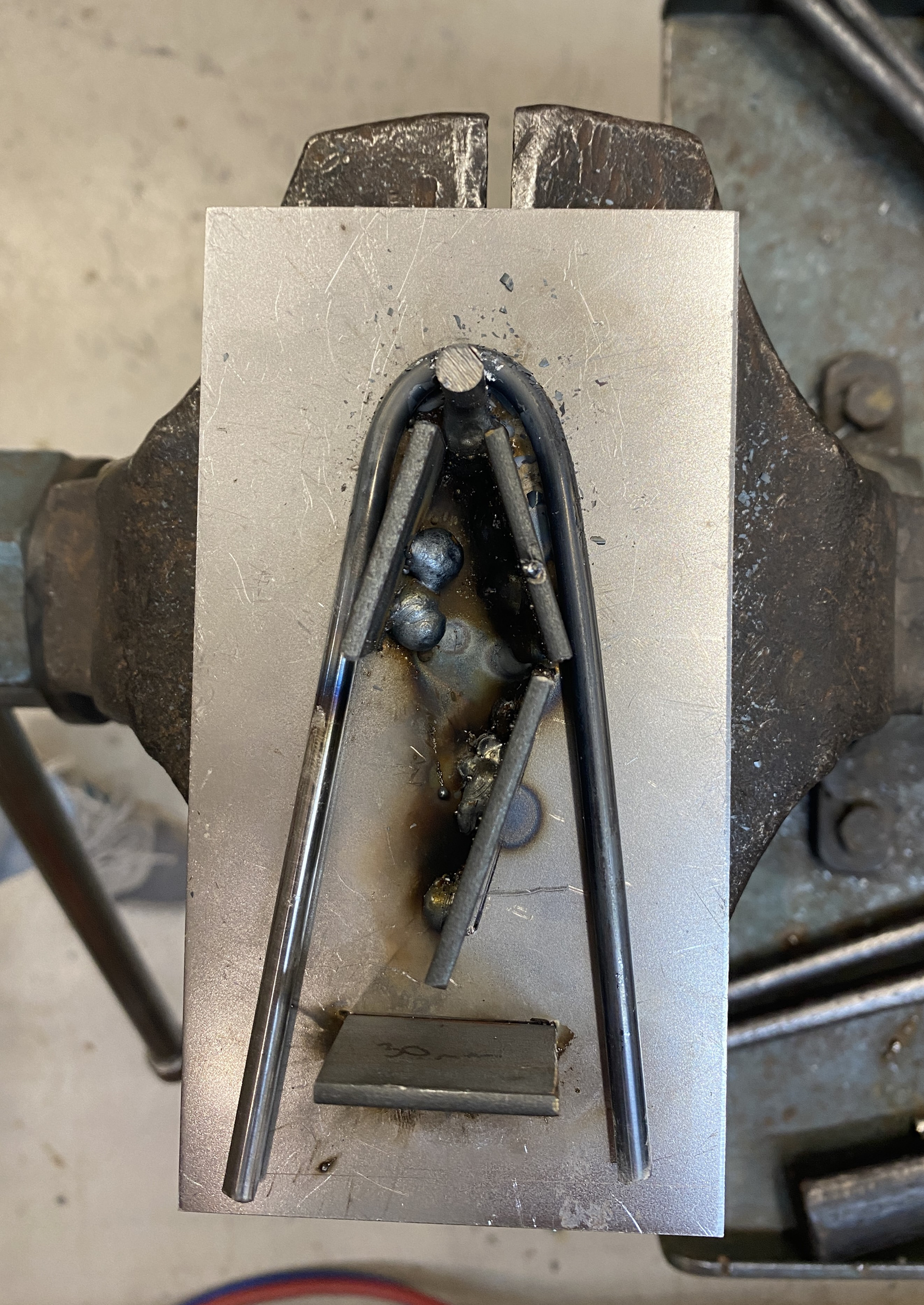

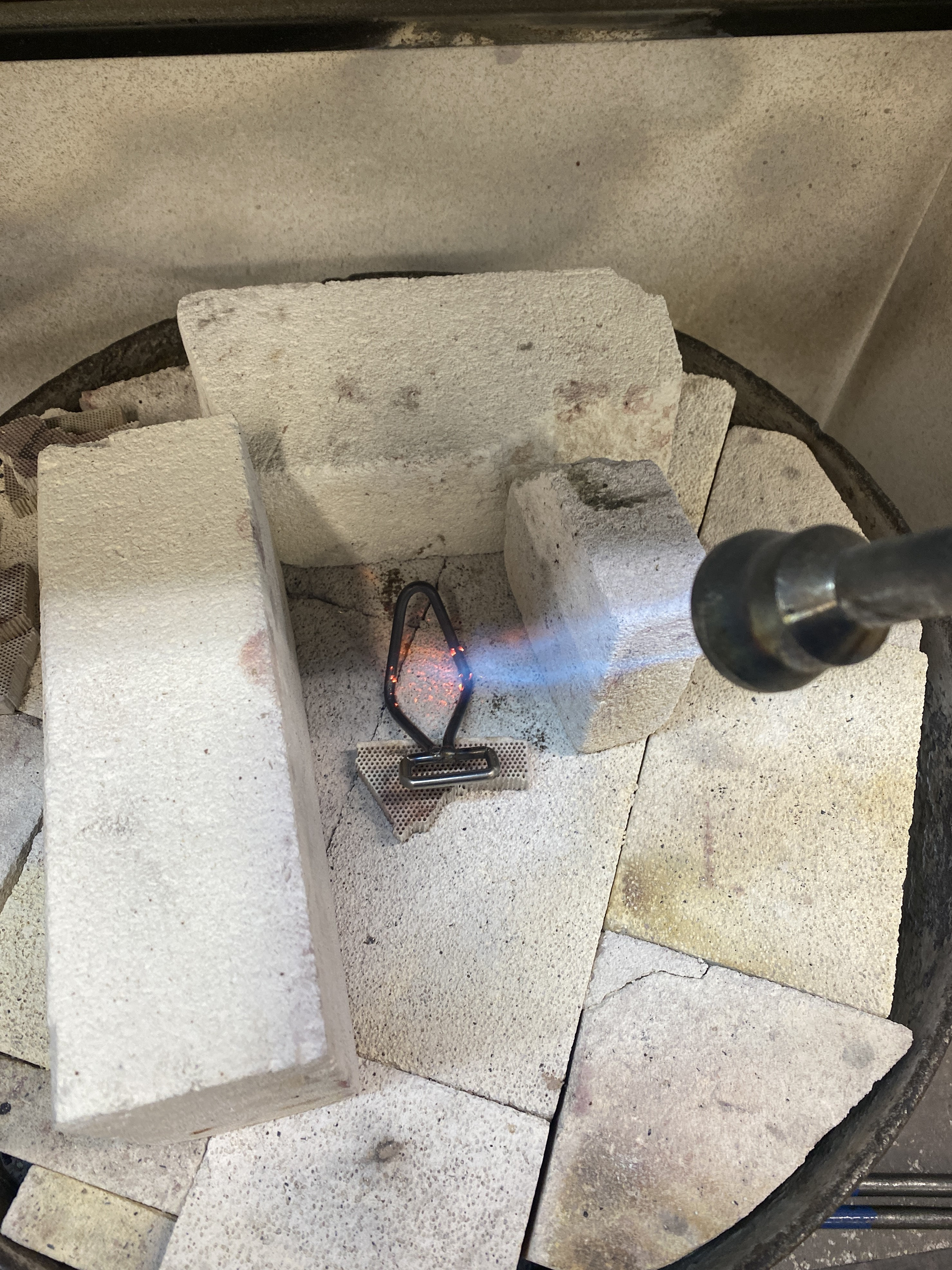
To bend the diamond section, I returned to my jigs. I had previously made almost the whole jig that was required to bend the shape. I started in the centre and formed the top V using tongs to push the rod into place evenly. I found that the jig was slightly flawed, the empty section between the top rod and the pieces of flat bar. When I put pressure on the work around this area it causes it to slightly bend outwards misshaping the straight sections of the diamonds. I found that heating the piece and hammering it against the table of the leg vice worked to shift this back into square.
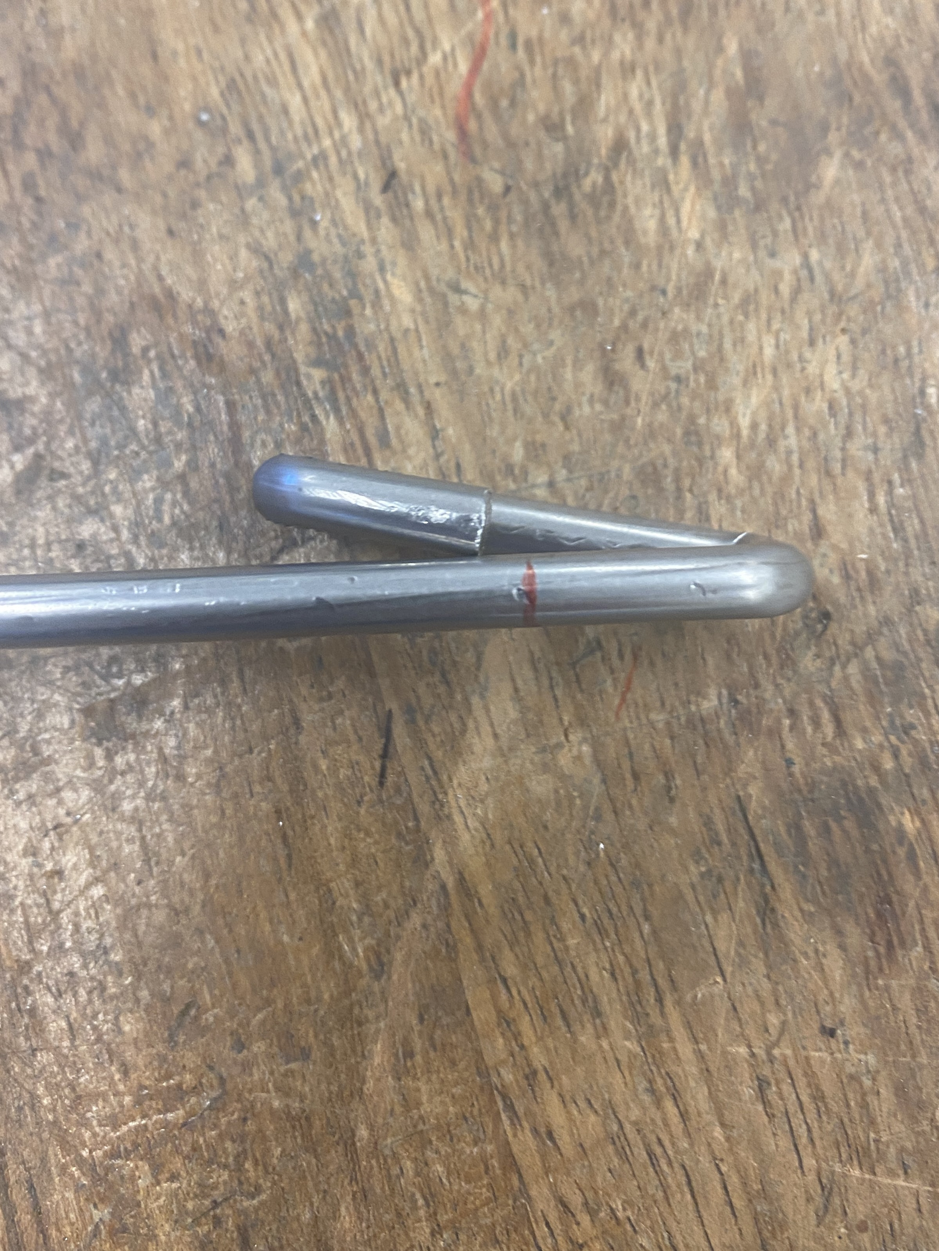
I then formed the lower half of the diamond using the jig. I had to flip the piece over as the jig was incomplete. As the rods met in the same place, I bent one over the other. I cut off the excess using a hacksaw.
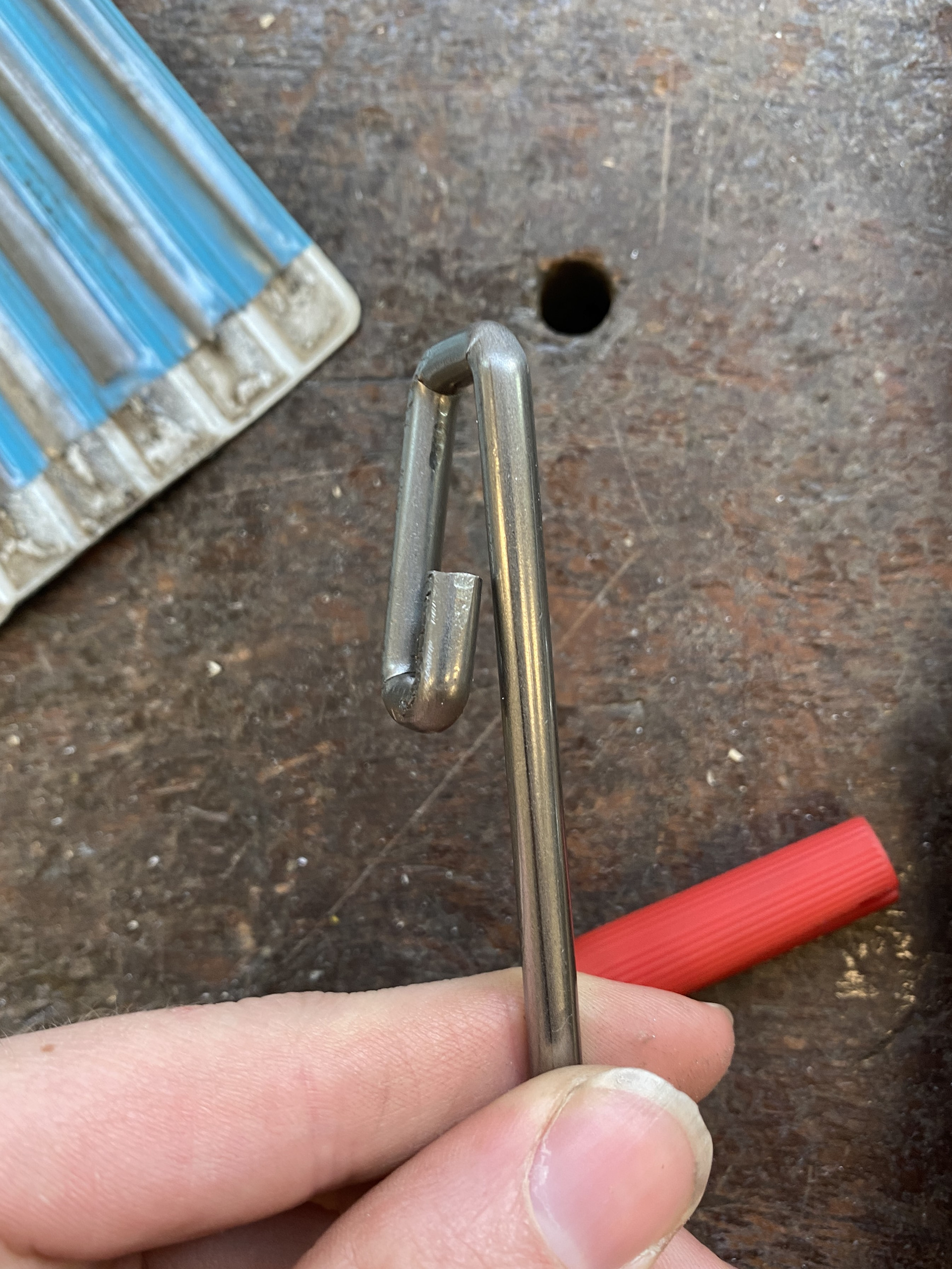
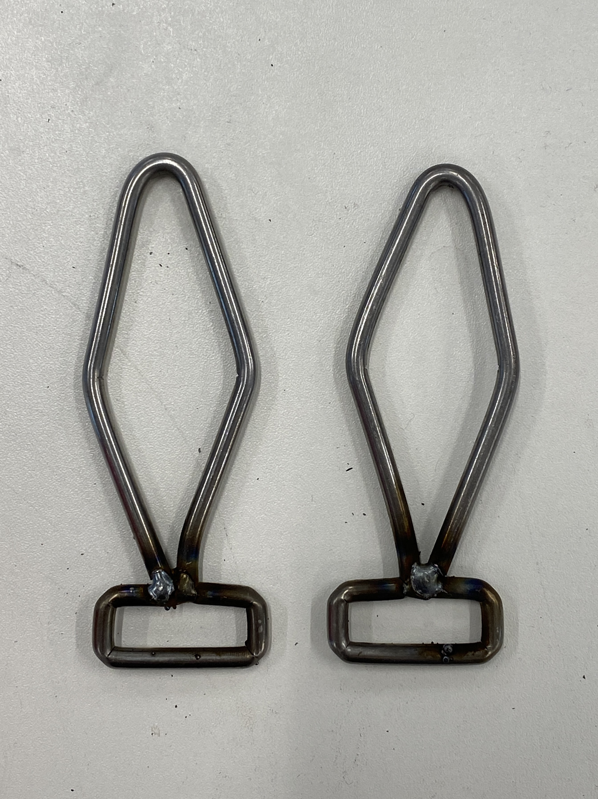
I then welded the two pieces together ensuring that there was good penetration for a strong connection. I then filed off the excess to create a smooth transition. Finaly, I bent the hook over using tongs and a 10mm rod.
I found that my welds were secure but there were some small gaps between tacks. This is an area that I need to improve through welding practice.
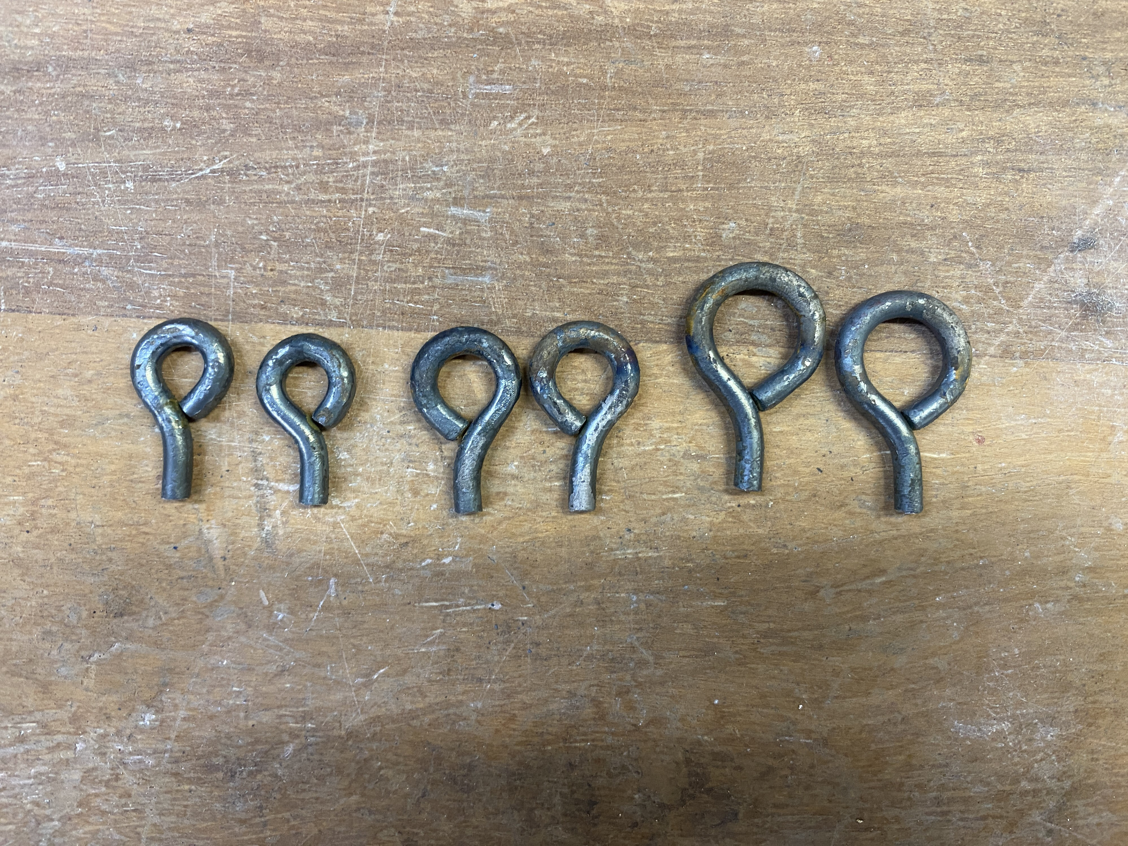
I forged the eyelets as done previously and then cut the excess rod off using a hacksaw. I then welded the eyelets to the rectangles by placing the rectangles in the vice and holding the eyelets in a g-clamp. This resulted in a centrally placed connection but the welding tended to pull the eyelets out of square. I fixed this by heating the piece up and placing it in the leg vice and realigning the eyelet using flat tongs.
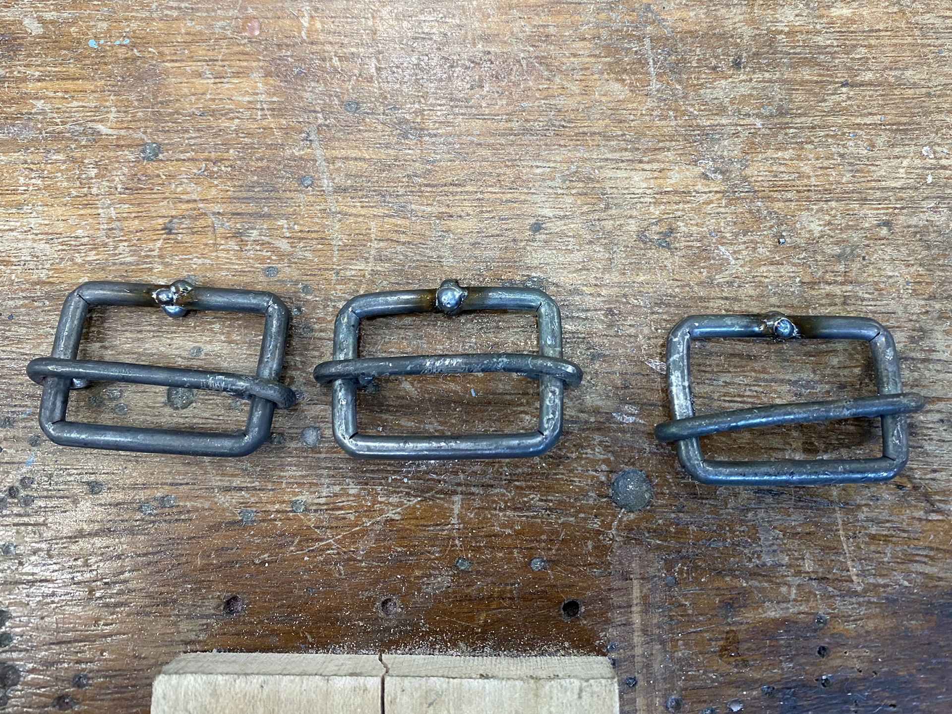

To create the rectangles of the slider, buckle previously I started in the corner, this resulted in imperfections. As I had refined the sequence to bend the rectangle portion of the other handwear, I replicated it for the slider buckle. This also meant that there was no awkward connection between the rods.
I also changed how I formed the central rod. I tested forming this first using 3mm aluminium wire and pliers. This gave me an order of operations but also the exact length required to bend both eyelets with minimal gaps (70mm). I formed a section of the first eyelet around a 4mm rod in the leg vice leaving enough room to remove it from the side, so that it could be placed onto the enclosed rectangle. I then heated up the eyelet with a small flame focusing the heat so that only it would move when I close it up using the tongs. I repeated this on the other side to wrap the rod around and complete both eyelets.
The completed hardware.